

A double pole push button switch should be specified as two separately documented control-circuit actions operated by one mechanical press. Before choosing hardware, define the function and contact state for each pole, then confirm that the selected device, panel drawing, and control design support the requirement. A common actuator does not by itself prove isolation, load duty, cross-voltage compatibility, or safety-function suitability.
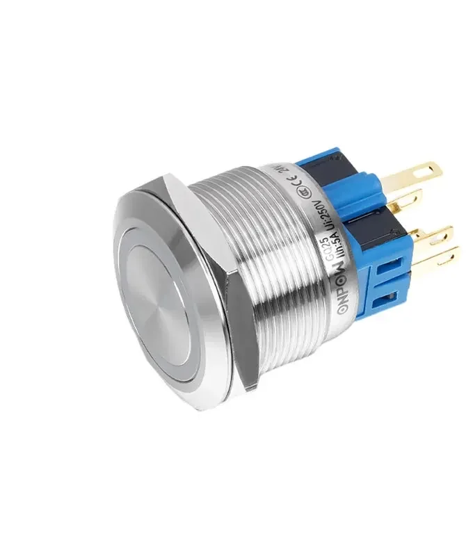
Part 1. Define the two-circuit decision before selecting hardware
The word “double pole” points to two switched poles, but a purchase request still needs to say what each pole is intended to do. One pole might carry a control input while another supports a separate interlock or indication condition. Those descriptions cannot be inferred from pole count alone.
Write a one-line function statement for each circuit before comparing push-button configurations. The statement should identify the controlled device or input, the required contact state at rest, the state after actuation, and whether both actions must occur at exactly the same mechanical operation. This record helps designers, panel builders, and suppliers discuss the same requirement.
| Decision to document | Why it matters | Do not assume |
|---|---|---|
| Circuit A function | Defines the first controlled action | That it matches circuit B’s voltage or duty |
| Circuit B function | Defines the second controlled action | That two poles mean a safety function |
| Contact state at rest | Distinguishes NO, NC, or other required state | That all poles use the same state |
| Operating action | States momentary or maintained need | That every product family offers both |
| Mechanical relationship | States whether one press must act on both | That electrically separate means system-compatible |
Search discussions often begin with a simpler phrase: “one pushbutton for two separate circuits.” The useful design response is not to provide a generic wiring shortcut; it is to retain the two functions as separate documented requirements while selecting a mechanically linked operator.
Part 2. Read pole, throw, and contact-state language correctly
Pole count describes how many circuits a switching device can control. Throw and contact-state terms describe how each pole changes connection state. A buyer should keep these terms separate because they answer different questions in a quotation or drawing review.
Double pole is not automatically the same as DPDT. DPDT describes a particular double-pole, double-throw arrangement, whereas a double-pole push button can have another documented contact arrangement depending on the selected product. Use the DPDT vs SPDT guide for that vocabulary comparison, then return to the selected part drawing for the actual configuration.
| Term | What it identifies | Buying implication |
|---|---|---|
| Pole | A separately switched circuit path | Record the purpose of every pole |
| Throw | The connection alternatives for a pole | Match the contact sequence to the control logic |
| NO / NC | Contact state under the defined rest condition | Define the condition in the documentation |
| Momentary / maintained | Mechanical operating behaviour | Match the action to the control requirement |
| Terminal form | Physical connection interface | Check wire, connector, and rear-space needs |
Important: Pole count cannot establish that two circuits can be combined, that their voltages are compatible, or that a push button fulfils a safety function. IEC 60947-5-1 gives the general context for low-voltage control-circuit devices; confirm the complete machine-control design and selected device documentation before release. (IEC 60947-5-1)
Part 3. Keep each circuit’s function separate in the control record
When a single actuator affects two circuits, the drawing should identify both functions at the point where the operator is shown. This creates a clearer review than a single note such as “double pole,” which leaves the actual contact logic and circuit purpose unknown. It also helps the panel team avoid reversing one circuit’s terminal assignment during assembly.
The record can be brief, but it should be unambiguous. Include the circuit reference, the required state before and after press, the signal or controlled element, and the relationship between the two actions. Where the two circuits use different conditions or supplies, the project documentation must explicitly define that design rather than relying on an operator’s appearance.
| Control record field | Circuit A example field | Circuit B example field |
|---|---|---|
| Drawing reference | Input or control reference | Separate input or control reference |
| Required state | State at rest and after press | State at rest and after press |
| Contact designation | Selected drawing field | Selected drawing field |
| Terminal identification | Terminal reference from the selected part | Terminal reference from the selected part |
| Functional relation | What the common press must do | What the common press must do |
The push button switch contact terminal configurations article can help a buyer read common terminal vocabulary. It should not be used to assign a contact arrangement to a model that has not been selected.
Part 4. Map terminals and operating action to the selected drawing
Terminal layout matters as much as pole count. A panel build needs enough rear access to route conductors, fit connectors, inspect markings, and service the operator without forcing wires against a door or bracket. Confirm the terminal direction and body depth on the selected drawing.
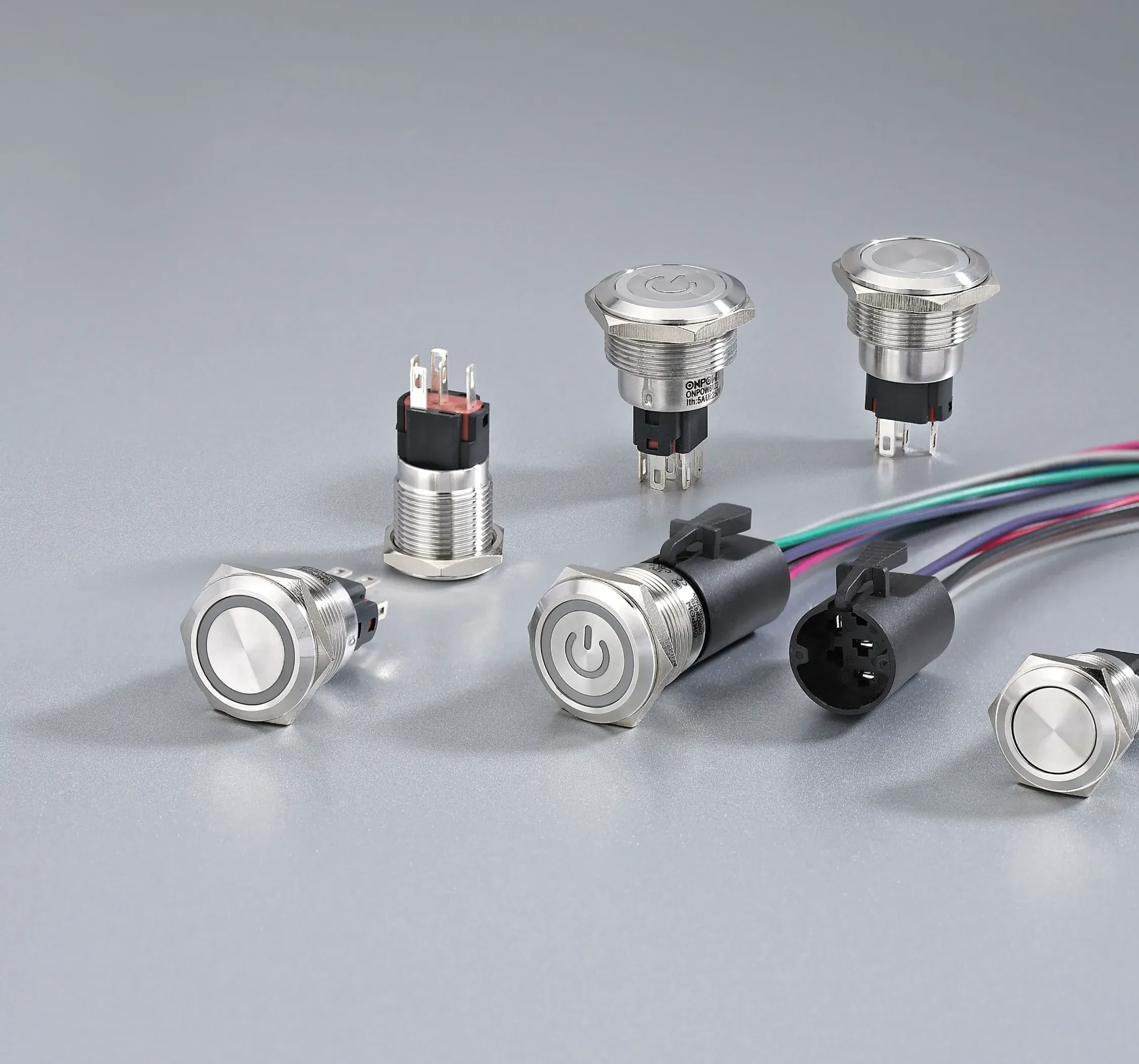
Mechanical action also deserves a clear entry in the requirement. If a press is intended to return when released, that condition should be stated. If the control behaviour relies on retention, reset logic, or another system element, record the requirement without assuming that a family image or a generic term determines the mechanism.
Mounting information also has a defined reference. Keep the panel cutout, thickness, and terminal envelope on the same released drawing as the two-circuit description, so the electrical notes and mechanical interface are reviewed together.
Part 5. Review panel layout and the fields that belong in the quote
Before requesting a quote, resolve the operator’s front-panel position and the rear wiring envelope. The two-circuit requirement should travel with those mechanical inputs. This lets a supplier assess the configuration without trying to reconstruct the intended circuit behaviour from an incomplete product name.
| Two-circuit details to provide | Why the supplier needs it | Common mistake avoided |
|---|---|---|
| Function of each pole | Confirms the required contact logic | Describing only “double pole” |
| Rest and actuated contact states | Aligns the operating requirement | Mixing NO and NC assumptions |
| Momentary or maintained action | Aligns operator behaviour | Using an unspecified actuation mode |
| Panel cutout and thickness | Confirms mechanical installation | Ordering before fit review |
| Rear section and terminal access | Confirms wiring and service space | Discovering interference after assembly |
| Quantity, destination, and documents needed | Frames quotation review | Omitting procurement conditions |
For an RFQ, send this record with the controlled panel drawing and circuit references. Do not include unverified statements about direct-load duty or system safety. If a project needs a protective function, its controls must be assessed within the complete machine design and applicable requirements.
Part 6. Ask ONPOW about GQ25 only after the two-circuit record is complete
The ONPOW GQ25 series is a relevant family to discuss when the released requirement calls for a 25 mm metal operator and the page-level context includes dual control circuits. That is a starting point for confirmation, not a statement that every GQ25 SKU shares the same contacts, terminals, action, rating, or certification.
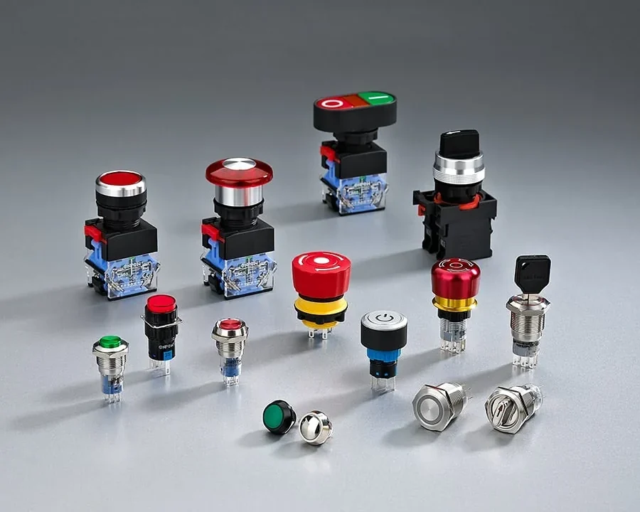
Provide ONPOW with the drawing, both circuit-function notes, required contact states, operation type, panel dimensions, quantity, destination, and required documentation. Ask the sales team to confirm the selected SKU against those inputs. This keeps the two-circuit decision visible through the quotation process rather than reducing it to a generic switch term.
The 25 mm push button switch guide provides adjacent sizing context. For wider documented product-selection topics, browse the ONPOW Blog.
Frequently Asked Questions
What is a double pole push button switch?
It is a push-button switching arrangement with two poles, so the requirement must identify the function and contact state of each separately. The selected drawing defines the actual terminal and operating configuration.
Does double pole mean two independent circuits?
It indicates two poles, but the system-level electrical relationship must be defined by the control design. Do not assume compatible voltages, isolation, duty, or protective-function suitability from pole count alone.
Is a double pole push button the same as DPDT?
Not necessarily. DPDT is one specific double-pole, double-throw description. Confirm the selected product’s contact arrangement instead of using the terms as interchangeable labels.
What contact information should I put on the drawing?
List the function of each pole, required contact state at rest and after actuation, terminal identification, operating action, and the panel reference where the operator is mounted.
Can one press control circuits at different voltages?
That question requires a documented control-design review. A mechanically common press does not by itself prove that the circuits can be combined or that the selected device is suitable.
Which ONPOW product family should I ask about?
If the requirement calls for a drawing-confirmed 25 mm metal operator with dual control-circuit context, ask ONPOW about the GQ25 series. Confirm the actual SKU’s contacts, terminals, action, and documentation before purchase.



