

If your project already has a finished control-panel face, a panel-mounted push button may be the cleanest route. If operators must be added to a machine frame, guard, skid or remote station, a push button switch box can create the operator surface and the protected wiring volume in one assembly.
The key question is not “Which button looks better?” It is: Does the equipment already have an approved operator surface? That answer determines whether you are specifying a device into a panel or defining the panel around a box.
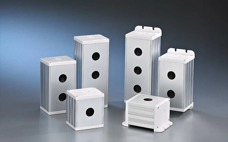
ONPOW metal push-button box family image; confirm the exact hole pattern and drawing for the requested model.
The difference in one minute
A panel-mounted push button operator passes through a prepared opening in an existing panel or cabinet door. The panel, its thickness, rear space and cable route already exist; the operator must fit them.
A push button switch box is an enclosure or control station that creates a separate operator surface. The box determines the available hole layout, cable-entry options, internal space and service access. It may be mounted on a machine or structure, but its suitability still depends on the complete installation.
| Decision point | Panel-mounted operator | Push button switch box |
|---|---|---|
| Operator surface | Existing cabinet, console or machine panel | New surface supplied by the box |
| First mechanical input | Finished cutout, panel thickness and rear clearance | Box hole pattern, usable depth, cable entries and mounting points |
| Wiring volume | Shared with the host panel | Dedicated volume, subject to the box drawing |
| Service question | Can the operator and terminals be reached behind the panel? | Can the box be opened and wiring serviced without removing the station? |
| Expansion | Limited by spare panel area and internal clearance | Limited by available holes, box size and the selected family |
| Common failure mode | Front bezel fits but terminals or wire bend collide behind the panel | Holes fit the buttons but cable entry, cover access or mounting does not fit the machine |
Neither architecture is automatically safer, more durable or more suitable. Those conclusions require the exact product evidence and the installation conditions.
Choose the host panel when the interface already exists
Use a panel-mounted operator when the equipment drawing already controls the operator location and there is sufficient rear space for the body, retaining hardware, contact block and conductors. The ONPOW panel specification guide recommends separating the visible interface from the circuit decision: a bezel or illuminated lens is not proof of a particular contact arrangement.
Before asking for a model, record:
- the approved cutout or hole pattern;
- panel thickness and front-surface constraints;
- rear keep-out, terminal direction and wire-bend space;
- momentary or maintained action;
- required NO/NC contact logic and whether a lamp circuit is separate;
- terminal or connector preference; and
- the environmental and documentation requirements that the exact model must satisfy.
For the detailed measurement sequence, see How to Specify a Panel-Mounted Push Button Switch. That page addresses the device-to-panel fit; this article addresses the earlier architecture choice.
Choose a box when the operator surface is missing or remote
A box is useful when the machine has no suitable panel opening, when operators need to be grouped at a remote station, or when a panel builder wants a defined enclosure volume rather than several ad-hoc cutouts. The box can simplify the physical concept, but it does not remove the engineering work.
Check the box as an assembly boundary:
- Hole pattern: Is the box offered with the diameter and number of openings required by the operator family? Do not assume a nominal “22 mm” label proves every bezel, nut or contact block will fit.
- Usable depth: Will the operator body, contact blocks and wire bend remain clear of the cover and side walls?
- Cable entries: Where will conductors enter, and can the entry route be maintained without compromising service access?
- Mounting: Does the mounting method suit the machine frame and leave the cover removable?
- Operating action: Are the requested momentary, maintained, selector or emergency functions supported by the exact operator models selected?
- Environment and evidence: Which enclosure and operator ratings or certifications are actually required, and where is the model-specific evidence?
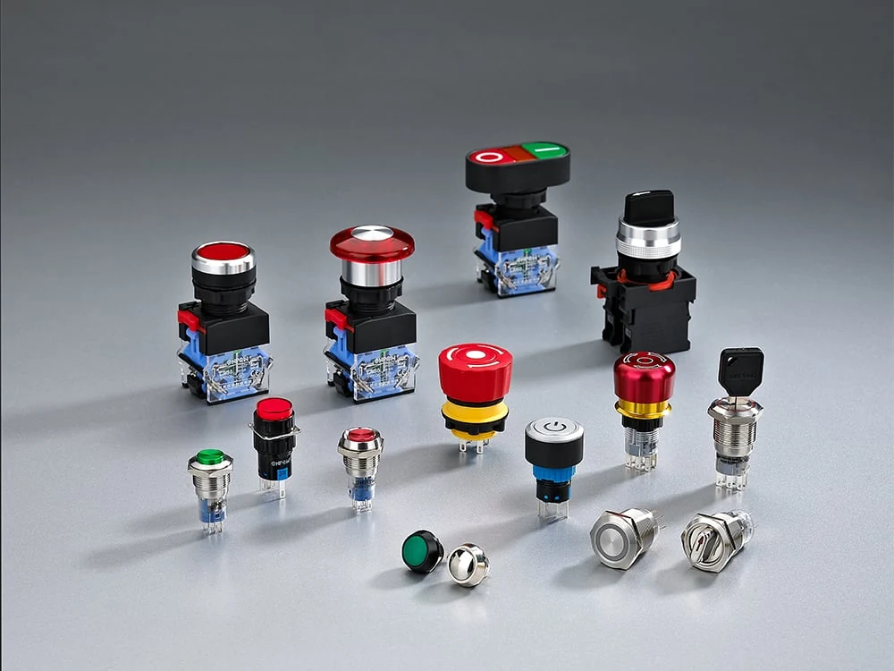
Use a panel-mounted operator image to explain the device boundary; use its exact model drawing before freezing the panel cutout.
Keep the electrical decision separate from the box decision
The box is a mechanical and environmental boundary. It does not choose your control logic. Define the operator action and circuit independently:
- A momentary operator changes state while actuated; a maintained/latching operator stays in its new state until actuated again.
- NO and NC describe the contact state in the defined normal condition. Match the requested logic to the exact contact block or switch model.
- An illuminated operator may provide indication, but its lamp circuit and switching contacts still need separate review.
- A contact rating from one model or family cannot be transferred to another model because the actuator shape looks similar.
For start/stop layouts and contact-routing context, see Dual Push Button Switches for 22mm Panels. It is a layout-specific follow-on, not a substitute for the box-versus-panel decision here.
A practical selection workflow
1. Freeze the operator location
Mark the controlled location on the machine or panel drawing. If the location is already cut into a cabinet door, begin with the panel route. If the location is a remote station or a new surface, evaluate a box.
2. Freeze the mechanical boundary
For a panel route, send the finished cutout, thickness and rear clearance. For a box route, send the required hole count/diameter, box mounting orientation, cable-entry concept and available service volume. In both cases, ask for the controlled drawing.
3. Freeze action and circuit inputs
State momentary or maintained action, NO/NC logic, contact quantity, illumination requirement, terminal preference and the control voltage/current conditions that the supplier must check. These are request inputs, not assumed product performance.
4. Review installation and maintenance
Check conductor exit, cover or panel removal, terminal access and the path for inspection. A front-facing layout that cannot be wired or serviced is not a complete selection.
5. Ask for model-specific evidence
Request the dimensional drawing, wiring/contact information and any required environmental or certification documents for the exact configuration. If a requirement is unknown, leave it open rather than filling it with a catalogue inference.
ONPOW box routes for the next request
ONPOW publishes separate Metal Push Button Box and Plastic Push Button Box family pages. The metal page lists an aluminium-alloy box family and a Ø16/19/22 hole-diameter field. The plastic page lists a PC box family with a Ø22 hole-diameter field and example identifiers such as BXB-3/22/W, BXB-2/22/W and BXB-1/22/Y.
Those fields are useful routing evidence, not a blanket fit approval. Send the box family, operator model, hole layout, wiring requirements, environment and required documents together. ONPOW can then confirm the exact configuration against its product drawing. If the project already has a controlled panel opening, start with the ONPOW Push Button Switch category and the panel-mounted route instead of adding a box by default.
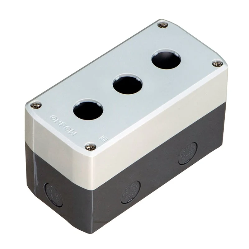
ONPOW plastic box product image; the published Ø22 field is family-level routing evidence and still requires model confirmation.
The short RFQ input list
Send these items so a supplier can answer with evidence:
- existing panel or proposed box location drawing;
- cutout/hole pattern and panel or box thickness;
- rear or internal clearance and cable-entry plan;
- operator action, NO/NC logic and illumination requirement;
- terminal/connector preference;
- operating environment and documents required; and
- quantity, target configuration and any open questions.
References
- ONPOW Push Button Switch category — official product pathway.
- ONPOW Metal Push Button Box — metal family, published hole-diameter field and example models.
- ONPOW Plastic Push Button Box — PC family, published Ø22 field and example models.
- How to Specify a Panel-Mounted Push Button Switch — cutout, thickness, rear clearance, contacts and service checks.
- How to Choose a Push Button Enclosure That Actually Fits — enclosure fit and RFQ inputs; follow-on context.
- Dual Push Button Switches for 22mm Panels — layout-specific start/stop follow-on.
- Everything About Push Button Enclosures — general enclosure terminology and decision topics.
- Push Button Switches: Types and Selection Tips for Engineers — momentary/maintained, NO/NC and specification language.
- Button and Switch Basics — open/closed circuit and actuation definitions.



