

Selector switch types are defined by more than the number of visible positions. A useful specification states the operator form, two or three positions, maintained or spring-return action, key removal rules where applicable, contact arrangement in every position, mounting size, environmental protection, and electrical load. The front legend and handle direction must agree with the circuit and machine state. Choose the operator and rear contact system together, then test every position during commissioning rather than assuming a familiar symbol produces a familiar contact sequence.
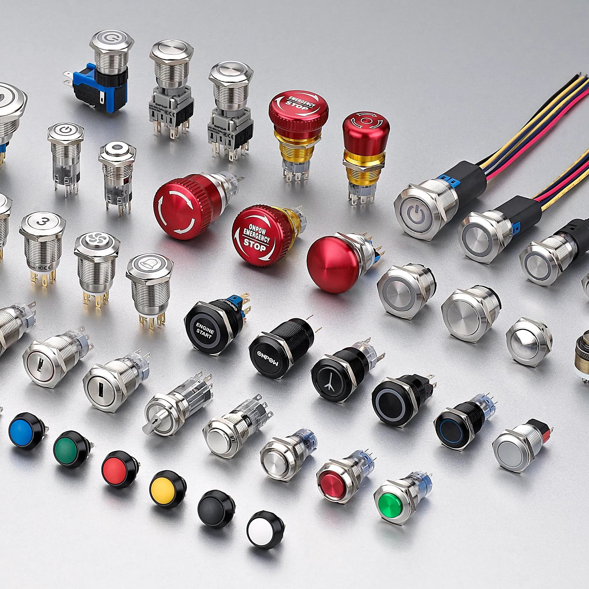
Selection rule: treat the device, actuator, contacts, enclosure, wiring, control logic, user, and machine motion as one system. Product examples illustrate form only; final suitability must come from the current documentation for the exact order code and from validation in the finished equipment.
How the mechanism works
Rotating the handle or key drives a cam that operates one or more contact blocks. A maintained mechanism stays in position. A spring-return mechanism moves back when released, sometimes from one side and sometimes from both. Contact timing may be break-before-make or another documented sequence. The visible pointer does not reveal the rear contact truth table, so the exact model diagram is essential.
Selection criteria at a glance
| Decision area | What to verify | Engineering reason |
|---|---|---|
| Positions | Define two, three, or other positions and their permitted angles | The operator must match the state machine. |
| Return action | Specify maintained, left return, right return, or both-side return | Return behavior changes how commands persist. |
| Operator form | Choose knob, lever, long handle, flush form, or key by user and access needs | Ergonomics and authorization are separate requirements. |
| Key rules | Define insertion and removal positions and key management | A key switch is access control, not automatic safety validation. |
| Contact truth table | List every contact state in every selector position | Never infer logic from the front pointer. |
| Contact timing | Check make/break sequence during transitions | Momentary overlap or gap may affect control logic. |
| Mounting and depth | Verify cutout, anti-rotation feature, rear blocks, and wiring space | Panel diameter alone is insufficient. |
| Legend and color | Use labels that match the machine function and user language | Clear marking prevents mode-selection errors. |
This table is intentionally qualitative. Numerical limits, ratings, torque, force, travel, environmental claims, and endurance values must be taken from the current datasheet and evaluated under the application conditions.
Detailed selection process
Positions
What to verify: Define two, three, or other positions and their permitted angles. The operator must match the state machine. The requirement should be written in the project specification and traced to the exact model drawing or datasheet. Review worst-case tolerance, wear, contamination, maintenance access, and foreseeable misuse. If the available documentation does not define the boundary, keep the point open for supplier confirmation and sample testing rather than substituting an assumption.
Return action
What to verify: Specify maintained, left return, right return, or both-side return. Return behavior changes how commands persist. The requirement should be written in the project specification and traced to the exact model drawing or datasheet. Review worst-case tolerance, wear, contamination, maintenance access, and foreseeable misuse. If the available documentation does not define the boundary, keep the point open for supplier confirmation and sample testing rather than substituting an assumption.
Operator form
What to verify: Choose knob, lever, long handle, flush form, or key by user and access needs. Ergonomics and authorization are separate requirements. The requirement should be written in the project specification and traced to the exact model drawing or datasheet. Review worst-case tolerance, wear, contamination, maintenance access, and foreseeable misuse. If the available documentation does not define the boundary, keep the point open for supplier confirmation and sample testing rather than substituting an assumption.
Key rules
What to verify: Define insertion and removal positions and key management. A key switch is access control, not automatic safety validation. The requirement should be written in the project specification and traced to the exact model drawing or datasheet. Review worst-case tolerance, wear, contamination, maintenance access, and foreseeable misuse. If the available documentation does not define the boundary, keep the point open for supplier confirmation and sample testing rather than substituting an assumption.
Contact truth table
What to verify: List every contact state in every selector position. Never infer logic from the front pointer. The requirement should be written in the project specification and traced to the exact model drawing or datasheet. Review worst-case tolerance, wear, contamination, maintenance access, and foreseeable misuse. If the available documentation does not define the boundary, keep the point open for supplier confirmation and sample testing rather than substituting an assumption.
Contact timing
What to verify: Check make/break sequence during transitions. Momentary overlap or gap may affect control logic. The requirement should be written in the project specification and traced to the exact model drawing or datasheet. Review worst-case tolerance, wear, contamination, maintenance access, and foreseeable misuse. If the available documentation does not define the boundary, keep the point open for supplier confirmation and sample testing rather than substituting an assumption.
Mounting and depth
What to verify: Verify cutout, anti-rotation feature, rear blocks, and wiring space. Panel diameter alone is insufficient. The requirement should be written in the project specification and traced to the exact model drawing or datasheet. Review worst-case tolerance, wear, contamination, maintenance access, and foreseeable misuse. If the available documentation does not define the boundary, keep the point open for supplier confirmation and sample testing rather than substituting an assumption.
Legend and color
What to verify: Use labels that match the machine function and user language. Clear marking prevents mode-selection errors. The requirement should be written in the project specification and traced to the exact model drawing or datasheet. Review worst-case tolerance, wear, contamination, maintenance access, and foreseeable misuse. If the available documentation does not define the boundary, keep the point open for supplier confirmation and sample testing rather than substituting an assumption.

Application review
- Manual/automatic mode selection. Record the expected command, response, release behavior, abnormal condition, and acceptance evidence for the assembled machine.
- Local/remote control. Record the expected command, response, release behavior, abnormal condition, and acceptance evidence for the assembled machine.
- Forward/off/reverse command with interlocking. Record the expected command, response, release behavior, abnormal condition, and acceptance evidence for the assembled machine.
- Setup mode under controlled authorization. Record the expected command, response, release behavior, abnormal condition, and acceptance evidence for the assembled machine.
- Multi-position process selection. Record the expected command, response, release behavior, abnormal condition, and acceptance evidence for the assembled machine.
For every application, include startup, normal operation, shutdown, loss of power, restoration of power, maintenance mode, component replacement, and the faults identified by the risk assessment. A general control switch should not be treated as a complete safety function.
Commissioning checklist
- Freeze the requirement. State the intended action, normal condition, supply, load, motion, environment, and user.
- Match the order code. Compare the delivered part with the approved drawing, contact diagram, actuator, terminal style, and accessories.
- Inspect installation. Check alignment, fasteners, rear clearance, cable routing, strain relief, protection of live parts, and access for service.
- Test every state. Verify operation and release at tolerance extremes, expected speeds, loads, gloves, contamination, and environmental conditions.
- Test abnormal conditions. Include disconnected conductors, blocked or damaged mechanisms, power loss, contamination, and other credible faults.
- Record the result. Save model, revision, test method, observations, acceptance criteria, date, and approver.
Common mistakes
- Ordering by front appearance only. Prevent this by assigning the check to a drawing, datasheet, wiring record, or commissioning test with a named acceptance criterion.
- Assuming every three-position switch has the same truth table. Prevent this by assigning the check to a drawing, datasheet, wiring record, or commissioning test with a named acceptance criterion.
- Ignoring spring-return direction. Prevent this by assigning the check to a drawing, datasheet, wiring record, or commissioning test with a named acceptance criterion.
- Using key removal as the only safety control. Prevent this by assigning the check to a drawing, datasheet, wiring record, or commissioning test with a named acceptance criterion.
- Failing to test transition states. Prevent this by assigning the check to a drawing, datasheet, wiring record, or commissioning test with a named acceptance criterion.
What to include in an RFQ
Provide the application, target market, applicable standards, machine function, supply and load, control interface, contact logic, mechanical drawing, motion path, panel dimensions, cable method, environment, operating frequency, quantity, documentation needs, and sample-validation plan. Ask the supplier to identify assumptions and exceptions. ONPOW offers relevant products in its application-specific product family and the broader industrial control product range.
Related ONPOW guides
Authoritative references
- IEC 60947-5-1 control-circuit devices
- IEC 60529 degrees of protection provided by enclosures
- OSHA machine guarding requirements
- OSHA electrical safety requirements
Educational video
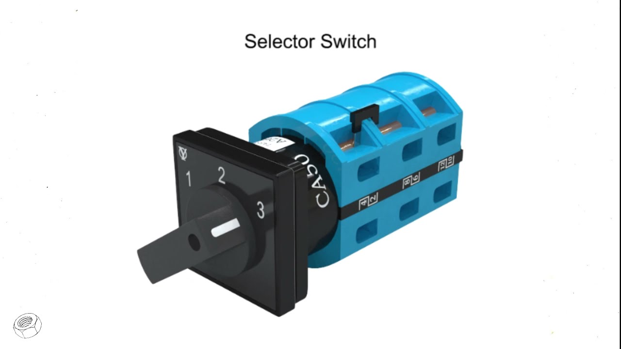
Selector Switch Explained in Animation by Engineering Easy provides general background. Project decisions still require the applicable standards and product documentation.
Frequently asked questions
What is a maintained selector switch?
It stays in the chosen position after the operator releases the handle.
What is spring return?
The mechanism returns from a specified position when released; the exact return directions must be ordered correctly.
Does a key selector make a machine safe?
No. It can limit casual access, but safety depends on the complete validated control system.
How is a selector contact diagram checked?
Create a position-by-position truth table and verify continuity on the exact assembled device before energizing the machine.
Final decision
Approve the component only when the documented mechanical, electrical, environmental, usability, installation, and maintenance boundaries all fit the assembled system. Resolve unknowns through current manufacturer information and testing before production release.



