

A push button mechanism converts a person’s press into a defined change of contact state, then either returns after release or retains a state according to its design. The visible operator, mounting assembly, sealing boundary and electrical contacts perform different jobs. Understanding those boundaries helps a panel builder specify and inspect the complete device without assuming that a metal head, an illuminated ring or a particular terminal count reveals its internal construction. Begin with the exact order-code drawing and required behavior. This article explains mechanism-related inspection and selection; it does not claim that every ONPOW model has the same spring, latch or internal layout.
Follow the action from the user’s finger to the circuit
The front operator receives the press. The device’s internal arrangement transfers that movement to one or more contact elements, changing the electrical path. On release, a momentary device is intended to return to its defined rest condition. A maintained device retains a condition until its specified release or reset action occurs. The exact sequence belongs to the selected configuration.
Separate these observations during inspection: the head moves, the head returns, the contact changes state, and the receiving circuit recognizes the change. A mechanism can appear to move normally while a connection problem prevents a useful signal. Conversely, a controller can retain a command after a correctly functioning momentary contact releases. Neither symptom alone proves a mechanical fault.
Use the drawing to establish what movement and contact sequence are expected. A smooth press is an observation, not a complete acceptance criterion. If timing, travel or force matters to the application, obtain the relevant published values and test method rather than relying on a person’s impression of a sample.
Keep operator, contact and illumination functions distinct
The operator is the part a person touches. The mounting assembly locates and retains the device in the panel. The contact arrangement defines the switched electrical paths. A lamp adds an indication function that may have separate terminals and supply requirements. These functions can be packaged together without becoming interchangeable specifications.
For example, an illuminated ring can identify a station in a dim workspace without indicating that its contact is closed. A flat metal head can describe an external form without demonstrating its internal contact action. A threaded barrel can provide a mounting interface without proving a particular resistance to rotation, vibration or water exposure in the completed panel.
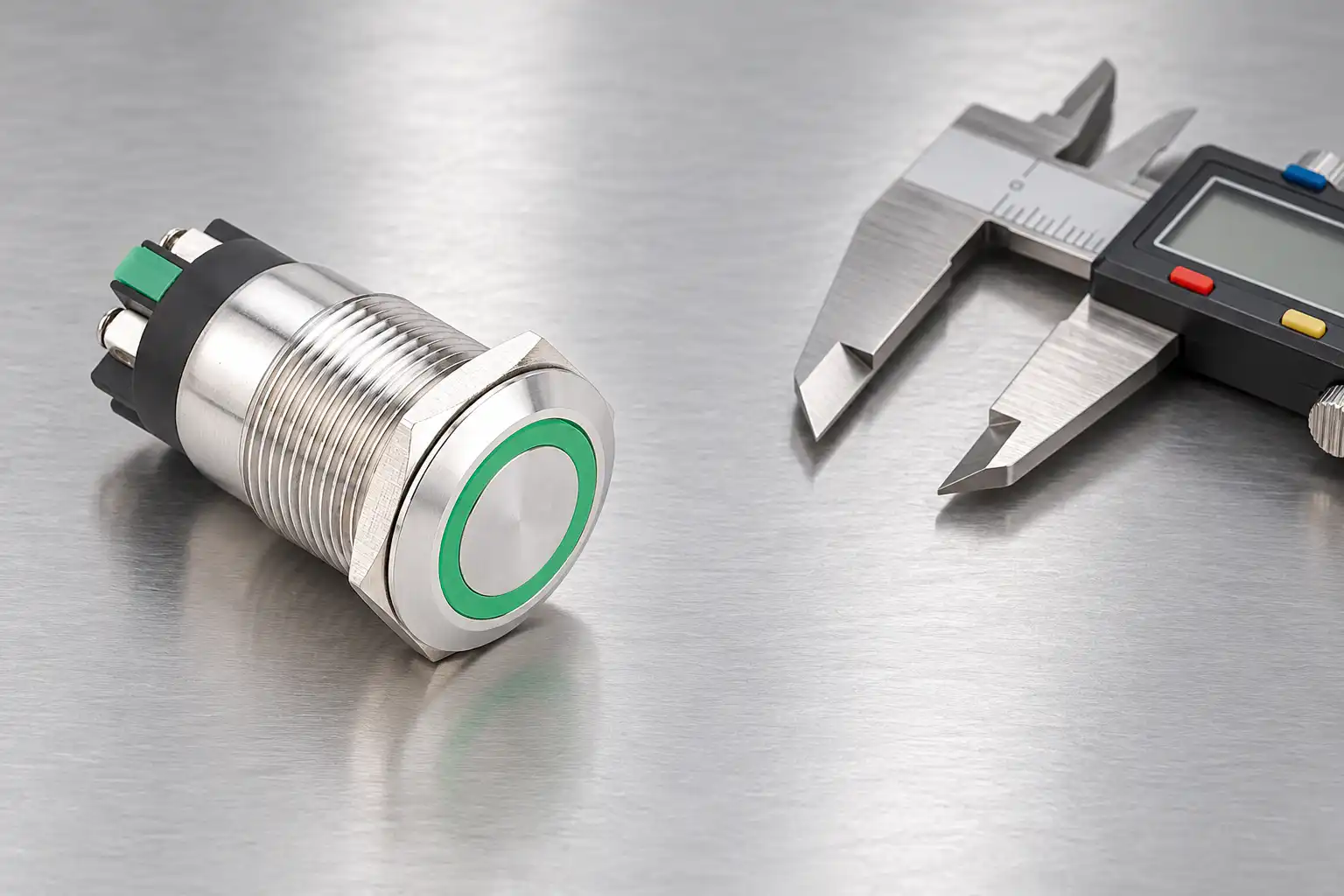
De ONPOW LAS1GQ screw-terminal ring-LED product provides a concrete external example: metal operator, threaded mounting body and rear connection region. Its photograph supports those visible features. Use the configuration drawing to identify the applicable contacts and lamp connections; the photograph is not an internal cutaway.

Specify momentary and maintained behavior precisely
For momentary service, write the required contact condition at rest, during operation and after release. If the function requires a short command, also describe how the control system interprets a sustained press. A button returning mechanically does not specify how software handles repeated or held commands.
For maintained service, describe the action that changes state and the action that restores it. Terms such as latching, alternate action, locking and self-locking can be used differently in informal enquiries. Ask for an operating sequence and exact order code rather than assuming that a familiar marketing term identifies the same mechanism across product families.
Do not confuse mechanical retention with a controller’s stored state. A momentary contact can initiate logic that remains active after release. A maintained contact can be electrically closed while the machine is prevented from acting by another condition. Keep the physical contact schedule and the control-function description together so maintenance staff can distinguish them.
Read mechanism-related specifications as separate limits
The table below is a qualitative review checklist. It gives no universal numerical limit because force, travel, life and mounting conditions depend on the selected device and test conditions.
| Item to review | What it describes | Evidence to obtain | Common mistaken inference |
|---|---|---|---|
| Operating action | Return or retention behavior | Configuration-specific operating sequence | Every metal button is momentary |
| Contact arrangement | State and number of switched paths | Terminal and contact drawing | Terminal count alone identifies the contacts |
| Operating force and travel | Defined mechanical input conditions | Values, tolerances and test reference | A comfortable sample establishes all limits |
| Mounting interface | How the device is retained in the panel | Cutout, stack thickness and installation method | Any fitting hole creates an approved installation |
| Environmental boundary | Which surfaces and conditions are protected | Product and assembly instructions | Front protection includes every rear connection |
| Endurance | Performance under defined cycling conditions | Mechanical and electrical life conditions | A cycle number guarantees a service interval |
Keep the distinction between a tested characteristic and an application requirement visible. If a published value does not describe the intended load or environment, ask for clarification. Do not silently extend it to a different duty because the external product looks similar.
Inspect fit without forcing the mechanism
A panel opening, mounting stack or neighboring component can interfere with normal operation. Confirm the released cutout, panel thickness, nut arrangement and rear clearance. Inspect alignment and access before tightening or connecting conductors. An operator that works freely on a bench may behave differently after an incorrectly assembled installation constrains it.
Follow the specified installation method. Do not compensate for an incorrect opening by applying extra tightening force, adding an unapproved stack of washers or forcing the rear housing against the enclosure. The mounting-nut torque guide explains why a generic torque assumption is not a substitute for the selected assembly instructions.
After installation, assess the intended movement using an approved inspection procedure. Look for interference from a legend plate, guard, cable bundle or neighboring operator. Keep the test conditions documented. If the product binds only after mounting, investigate the installation before concluding that its internal return arrangement needs modification.
Check the contact separately from the lamp
Identify terminal groups from the exact drawing with the circuit safely isolated as required. A continuity check on an appropriately isolated contact can show its rest and actuated states. It does not establish the lamp voltage, the contact’s full switching duty or reliable operation at a very small signal current. Those require separate documentation and evaluation.
Parallel paths in connected equipment can also confuse a measurement. A reading taken across a contact still connected to other circuit elements may describe more than that contact. Competent personnel should choose the isolation and test method. The contact-continuity interpretation guide discusses how to avoid treating a meter indication as a complete diagnosis.
General HSE electrical safety guidance provides context for safe inspection and competent work. Do not perform resistance tests on energized equipment or bypass protective functions to test an operator. The site’s approved procedure determines how the specific machine is made safe and returned to service.
Interpret return problems without guessing at hidden parts
If an operator fails to return as expected, first confirm that the delivered configuration is actually momentary. Then check for external interference, contamination, mounting distortion and damage. A retained state may be correct for a maintained configuration; a slow return can have several causes that cannot be identified from the head shape alone.
Do not open a sealed assembly, stretch a suspected spring, add lubricant or modify a latch unless the manufacturer provides an authorized service procedure. Such changes can affect contact action, sealing and predictable operation. A non-serviceable assembly may need replacement, but the cause still needs investigation so the same installation problem does not damage the replacement.
De industrial push-button sticking article focuses on that fault investigation. This mechanism overview instead establishes what to document before a fault occurs: expected action, contact sequence, installation conditions and the source of each requirement.
Separate mechanical life from electrical duty
Mechanical endurance and electrical endurance answer different questions. A device cycled under defined mechanical conditions is not thereby qualified for every connected load. Switching a load can introduce wear mechanisms that are not represented by a no-load movement test. The mechanical versus electrical life guide explains that distinction in more detail.
Do not convert a catalogue cycle figure directly into a guaranteed replacement interval. Actual duty includes operating rate, load type, environment, mounting, contamination and maintenance conditions. Establish an application-specific inspection or replacement approach with the responsible technical team. Preserve the test conditions behind any supplier endurance statement in the procurement record.
De IEC 60947-5-1 listing from Estonia’s national standards body identifies the context of electromechanical control-circuit devices. A standard’s scope is not evidence that a particular order code has a particular certification or application approval. Request the relevant product documentation when that evidence is required.
Turn the mechanism requirement into a useful RFQ
Send the required action and contact schedule, intended load or receiving input, lamp function, panel drawing, environmental conditions and expected operation pattern. Include any required force, travel or tactile characteristics as explicit requirements with their acceptance method. Avoid asking for an internal feature that the application does not actually need or that has not been verified for the selected family.
Request the complete order code, terminal drawing, installation instructions and applicable test evidence. Approve a representative sample against the released requirements and record any exceptions. A supplier can then propose a configuration based on defined behavior rather than infer the entire application from a photograph or a short phrase such as “metal push button.”
Veelgestelde vragen
Does every push button use the same spring arrangement?
No. Internal arrangements vary by design and operating action. Use the selected product documentation; an exterior photograph cannot establish the spring, latch or internal contact construction.
Does a head returning prove the electrical contact is correct?
No. Mechanical return and electrical contact state are separate observations. Check the specified contact sequence and the receiving circuit using an appropriate safe test procedure.
Can I turn a maintained button into a momentary one by modifying it?
Use an approved configuration rather than modifying an internal mechanism without a manufacturer-authorized procedure. Unapproved changes can affect predictable operation and other product characteristics.
What should I verify before replacing a sticking operator?
Confirm the order code, expected operating action, mounting conditions, interference and observed contact behavior. Investigate the installation and environment so a replacement does not inherit the same cause.
Meer leren
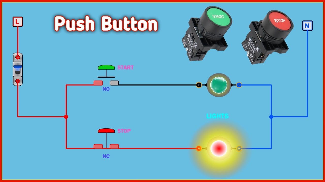
Educational animation of generic push-button operation and contact change; it does not document the internal construction of the pictured ONPOW model.
How the Push Button Works || Electrical Simulation — Electrical Simulation



