

A 12V or 24V key switch should be selected by what its contacts actually switch, not simply by the control-supply voltage. A keyed operator feeding a controller input, switching a relay coil or directly switching another load faces different electrical conditions. Confirm AC or DC duty, the load type, operating and inrush current, input compatibility, contact arrangement and any separate lamp supply. Low voltage does not automatically mean low current or harmless operation. For an industrial panel, separate the operator’s access function from the electrical circuit and ask the supplier to confirm the exact configuration against the real application.
Identify the circuit before choosing the switch
Start by drawing the boundary around the switch’s job. Does it provide a signal to a PLC, enable a control circuit, energize a relay coil or carry a load directly? A photograph and a voltage label cannot answer that question. The schematic should show what each contact connects and what happens in every key position.
For a controller input, the relevant requirements include input voltage and current, input architecture, contact suitability and the required state sequence. For a relay coil, consider the coil type, its actual operating requirements and the switching transient. For another load, request the relevant switching-duty information instead of applying a contact figure from an unrelated example.
Write the supply as more than “12V.” Identify DC or AC, the expected operating range and the conditions that may affect it. The switch supplier and controls designer need the actual application description before they can confirm a suitable version.
Contact ratings are specific to duty
A maximum voltage or a conventional thermal-current figure does not establish that a contact can interrupt every load at that value. Electrical ratings depend on the documented duty and conditions. Ask for the relevant rating for the proposed AC or DC circuit and load type.
DC and AC are not interchangeable labels. Do not assume that an AC contact rating can be copied to a DC application, or that reducing voltage permits an unlimited increase in current. Keep the published product information and the application evidence together in the selection record.
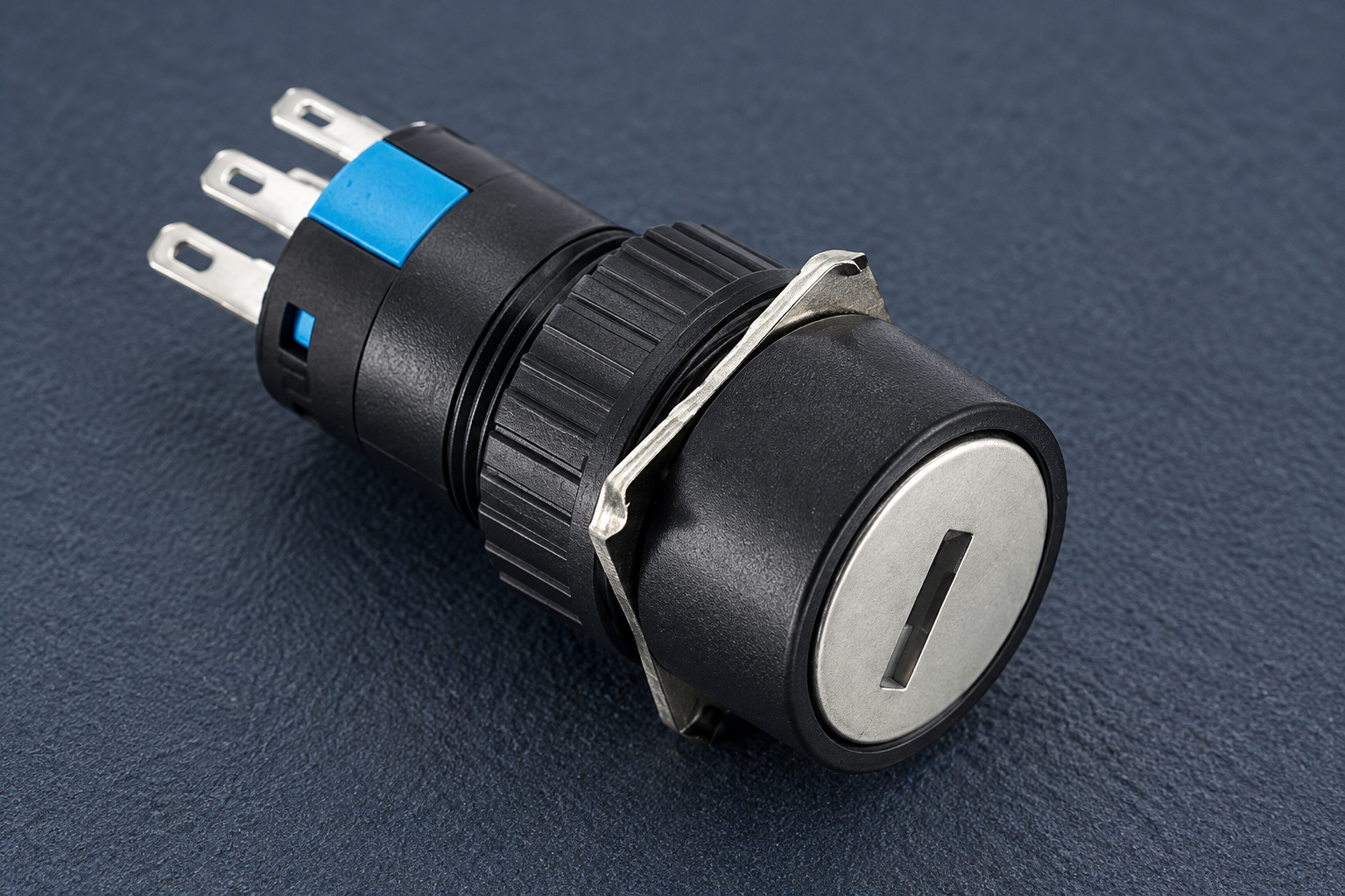
The ONPOW key and selector switch range provides the product starting point. Review the exact contact assembly and drawing with the supplier. The product illustration below identifies a real operator family; it does not demonstrate electrical performance at 12V or 24V.
Controller inputs need a signal-duty review
A small PLC input may operate at a much lower current than the contact’s conventional maximum rating. High-current capacity alone does not prove dependable behavior at the actual signal level. Request the contact’s suitability for the intended input and any specified minimum-load information.
The input module’s diagram also matters. Confirm the required connection architecture and common reference from the module documentation. Avoid a generic claim that any dry contact can be wired identically to every controller. Diagnostic features and the controller’s interpretation of transitions can affect the application.
If the switch is used for a mode request, document the difference between a requested state and an accepted state. The controller may reject a mode while another condition is unsatisfied. A key position does not necessarily prove that the machine has entered the corresponding operating mode.
The HSE control systems guidance provides wider context for considering the plant interface, logic and human interface together. For this task, its practical relevance is to check the input as part of the complete control sequence rather than approving a switch in isolation.
A selection table for 12V and 24V panels
The table below supplies questions and evidence requirements rather than assumed ratings. Complete it from the actual circuit and the exact product drawing.
| Application detail | Wat te verifiëren | Why the voltage label is insufficient |
|---|---|---|
| PLC or other electronic input | Input requirements and contact signal-duty suitability | Small input currents need their own compatibility review |
| DC relay coil | Coil data, switching duty and suppression arrangement | An inductive load can produce a transient when interrupted |
| Directly switched load | Operating, starting and interruption conditions | Current and load behavior can dominate selection |
| Illuminated operator | Separate lamp supply and connection instructions | Lamp voltage is not the contact switching rating |
| Mode or access selection | Contact table, maintained or return action, key removal positions | Electrical voltage does not define mechanical behavior |
| Power interruption | Controller response and approved restart sequence | A maintained key position can remain selected after power loss |
| Panel construction | Terminal type, clearance and mounting instructions | A suitable electrical rating does not ensure a suitable assembly |
Keep unknown items visible. If the load data or contact duty cannot be confirmed, request clarification before treating the proposed part as an equivalent replacement.
Inductive loads and suppression
A relay or solenoid stores energy in its magnetic field. Interrupting its circuit can create a transient. The circuit designer should select a suppression arrangement compatible with the coil, controller output and required release behavior. Do not turn this general principle into an unverified component recipe.
Suppression affects more than peak voltage. A chosen method can influence release behavior, and the machine’s timing requirements may matter. Follow the coil and control-system documentation and preserve any safety-related requirements. Do not recommend a diode for an AC coil or prescribe its orientation without the verified circuit.
For background, see the existing relay coil suppression guide. Check its scope against the actual coil before applying any example. The keyed operator’s role remains a separate selection: it may provide a request to an intermediate device rather than carry the coil current directly.
When selecting an intermediate relay or contactor, its presence does not remove the need to verify the key switch’s own duty. The command circuit still has a load and a switching sequence. Document both sides of the arrangement.
Lamp voltage belongs on a separate order line
An illuminated keyed operator may offer several lamp versions. Select the version matching the intended lamp circuit, including AC/DC restrictions and any polarity requirements. Never infer lamp connections from the number or position of terminals.
Specify what the lamp means. Supply available, mode requested and mode accepted are different messages. A light powered from the supply does not automatically confirm contact state or machine operation. If the indicator follows a controller output, define what that output establishes.
The related illuminated key switch selection guide addresses this display decision. The low-voltage article focuses on contact and circuit-duty selection, rather than duplicating lamp-message design.
Mechanical options still need precise specification
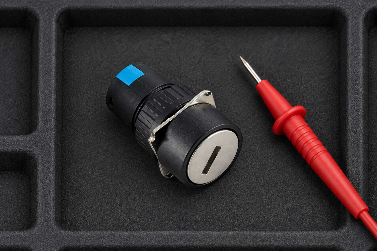
A low-voltage circuit does not determine the number of positions, return direction or permitted key removal positions. Define these requirements independently. For a maintained command, the key position can remain selected after the supply is interrupted. For a spring-return command, the physical operator returns but the controller’s reaction still depends on its logic.
The two-position key switch guide provides context for maintained selection. The momentary key switch guide explains why return action and controller response must be reviewed separately. Choose the version that matches the sequence, not the version that happens to have a familiar voltage in its listing.
Key removal requirements also affect access management. Decide who should retain the key and whether it must remain captive in a selected position. These are operating requirements, not electrical consequences of using 12V or 24V.
Low voltage does not replace isolation
A low control voltage can coexist with stored energy, powerful actuators and other hazardous supplies. An ordinary key switch can inhibit a request without isolating all energy. Maintenance needs the applicable equipment procedure and energy-control method.
The US hazardous-energy requirements in 29 CFR 1910.147 are relevant to that distinction. They should not be represented as a certification of a keyed operator. Apply the rules for the machine’s location and follow the responsible employer’s procedures.
Do not suggest that holding the operating key makes it safe to work on the machine. The key’s normal-control role and any authorized energy-isolation system must be documented separately. Where a safety-related function is involved, ordinary contact selection is only part of the required assessment.
Replacement checks and acceptance
Compare a proposed replacement with the original part and circuit. Review contact arrangement, relevant duty, terminal layout, operator action, lamp version and removal positions. A switch that fits the cutout may still change an important behavior.
With appropriate isolation and qualified procedures, verify the delivered mechanical and contact states against the approved drawing. Commission the control response under the equipment’s approved test conditions. Include release, power interruption and restoration where the operating sequence requires them.
Save the exact product identification and acceptance results. For an inquiry to ONPOW, send the schematic, supply details, input or load data, contact table and mounting requirements. This allows a specific configuration to be confirmed instead of asking a supplier to approve an undefined “12V key switch.”
Further learning: wiring and program interpretation
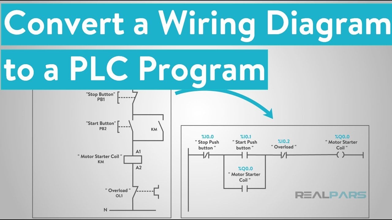
The RealPars lesson below connects basic wiring diagrams with PLC programming. It helps explain why a physical contact and an input decision are different parts of the application. It does not validate any particular low-voltage rating or machine safety function.
Common low-voltage selection questions
Is any key switch suitable for a 12V control circuit?
No. Check the actual AC or DC circuit, load type, current, switching duty and input compatibility. The supply voltage is one part of the application, not the complete requirement.
Does an AC rating establish a DC rating?
No. Use the relevant documented DC duty for the proposed application. Do not copy an AC figure or assume that a lower voltage permits unlimited current.
Is a high-current contact always appropriate for a PLC input?
Not automatically. Confirm suitability at the actual signal level and any stated minimum-load requirements. A conventional maximum-current figure does not answer the low-current question.
Can the lamp and contacts use different supplies?
That depends on the exact device’s circuit and approved configuration. Specify lamp supply and contact duty independently and follow the supplied connection diagram.
Does a 24V key switch isolate a machine for maintenance?
An ordinary control key switch does not necessarily isolate hazardous energy. Use the machine’s authorized isolation procedure and applicable requirements rather than relying on the operating key.



