

Przełącznik przyciskowy 8 mm to właściwe mikrowycięcie, gdy rysunek panelu przewiduje już średnicę Φ8, a gęstość przełączników jest ważniejsza niż rozmiar pola dla palca lub obszar oznaczenia. Średnicę otworu pod zamek, głębokość tylną, pola styków oraz rodzaj wyprowadzeń przed zablokowaniem kształtu główki, koloru diody LED lub grafiki.
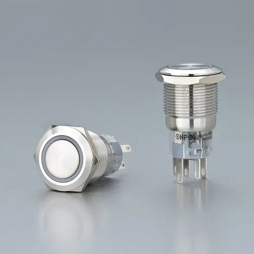
Część 1. Kiedy przełącznik przyciskowy 8 mm jest właściwym mikrowycięciem?
Mikropanele ulegają awarii, gdy zespoły wybierają średnicę ze zdjęcia w katalogu zamiast z rysunku drzwi. Wycięcie decyduje o narzędziach wykrawających, liczbie operatorów mieszczących się w rzędzie, rozmiarze okna legendy oraz o tym, która ścieżka rozbudowy pozostaje otwarta w przypadku późniejszej zmiany układu.
Traktować 8 mm (Φ8) jako najmniejsza droga o gęstości plastiku w kompaktowej linii ONPOW:
- wybierz 8 mm kiedy drzwi muszą zmieścić jak najwięcej punktów kontrolnych na najmniejszej powierzchni, a operatorzy nadal mogą niezawodnie trafić w cel;
- recenzja 10 mm kiedy nieco większy otwór poprawia zasięg bez przechodzenia do nowej rodziny akcesoriów — zobacz Porównanie przycisków 8 mm i 10 mm za ten kompromis;
- przenieść do 12 mm gdy dominują układy dwuobwodowe, większe opisy lub bardziej pobłażliwe cele dla palców – zacznij od Przewodnik po miniaturowych przyciskach 12 mm.
| Rodzina z wycinanek | Typowy cel panelu | Typowy kompromis |
|---|---|---|
| 8 mm (Φ8) | Maksymalna gęstość przełączników na mikro drzwiach | Najmniejsze okno celu operatora i legendy |
| 10 mm | Nieco większy zasięg niż 8 mm przy podobnych kompaktowych narzędziach | Mniejsza gęstość niż Φ8 przy tej samej szerokości drzwi |
| 12 mm | Kompaktowy panel HMI z tworzywa sztucznego z opcjami dwuobwodowymi | Większy ślad z przodu niż w układach mikro Φ8 |
Ten artykuł ma na celu ścieżka pozyskiwania przeznaczona wyłącznie dla 8 mm. Nie powtarza to pełnego porównania funkcji 8 mm kontra 10 mm – to zagadnienie należy do powiązanego artykułu podanego wyżej.
Mniejsza średnica nie oznacza automatycznie mniejszej przydatności elektrycznej. Obciążalność styków to cechy modelu, a nie gwarancje wielkości otworu.
Część 2. W jaki sposób podcięcie, głębokość tylna i przestrzeń na napis wpływają na wybór 8 mm?
Dopasowanie mechaniczne blokuje więcej projektów mikro-paneli niż wybór koloru. Przełącznik, który pasuje do schematu, nadal może kolidować z złączami, korytami kablowymi lub sąsiednimi wskaźnikami za cienkimi drzwiczkami.
Udokumentuj te dane wejściowe przed zapytaniem ofertowym:
- średnica otworu w panelu przednim (cel Φ8) i tolerancja;
- grubość panelu i zazębienie nakrętki lub spinki;
- długość tylnej części korpusu plus promień gięcia przewodu przy wyprowadzeniach stykowych;
- przylegające strefy zastrzeżone dla lamp, wyświetlaczy i zawiasów;
- dostęp dla operatora w rękawicach lub bez;
- grubość tabliczki opisowej i obszar do druku na tarczy 8 mm.
| Przegląd mechaniczny | Dlaczego to ma znaczenie przy Φ8 |
|---|---|
| Szablon wycinany vs szablon do dziurkacza | Zapobiega owalnym otworom, które blokują tuleję przy mikrośrednicach |
| Prześwit z tyłu | Zapobiega zwarciom po okablowaniu końcówek pinowych w płytkich puszkach |
| Rozmiar docelowy operatora | Mikrosiłowniki częściej zawodzą podczas uruchomienia, jeśli zasięg nie został przetestowany |
| Okno legendy | Podświetlane nasadki i etykiety tekstowe wymagają przestrzeni, której główka Φ8 może nie zapewnić |
Wskazówka: Dopasuj język klasy urządzeń w BOM do standardów obwodów sterowania, a następnie zweryfikuj rysunek montażowy producenta dla konkretnego SKU — normy definiują zakres, a nie wzór Twoich otworów (aparatura obwodów sterowniczych IEC 60947-5-1).
Z pola: Wątki na panelach często pytają, czy drzwi zaprojektowane już pod mikroprzyciski mogą nadal pomieścić tabliczkę opisową bez ponownego otwierania programu wycięć – to pytanie dotyczy problemu układu mechanicznego, a nie dowodu na to, że każdy siłownik Φ8 ma tę samą geometrię główki. dyskusja nad wzorem wycięcia w panelu przemysłowym
Jeśli operatorzy wielokrotnie nie trafiają w mikrocele podczas uruchomienia, rozwiązaniem jest zazwyczaj udokumentowane zwiększenie wykroju — a nie ciaśniejsza grafika na zbyt małym przycisku.
Część 3. Jakie pola elektryczne mają znaczenie przy Φ8?
Odczytuj pola katalogowe jako nazwane dowody, a nie przymiotniki marketingowe. W przypadku obwodów sterowniczych nabywcy zazwyczaj porównują napięcie izolacji, prąd termiczny, układ styków oraz oczekiwaną trwałość w określonych warunkach testowych.
ONPOW Strona serii LAS4 listy Ui 250 V i Ith 3 A dla rodziny tworzyw sztucznych Φ8. Na reprezentatywnych stronach modeli, takich jak LAS4F-11/, dodatkowe wymienione pola obejmują trwałość mechaniczną ≥200 000 cykli, elektryczne życie ≥50 000 cykli, i z przodu IP40. Traktuj każdą wartość jako pole wymienione na stronie dla cytowanego SKU — a nie jako dowód, że każde obciążenie indukcyjne jest zatwierdzone bez przeglądu użytkowania.
Pytania obwodowe, które wciąż blokują wybór mikroplastiku:
- Ile ścieżek NO/NC potrzebuje schemat w jednym siłowniku?
- Czy ta gałąź to komenda obwodu sterującego czy ścieżka zasilania?
- Czy oświetlenie będzie miało wspólną głębokość i okablowanie ze ścieżką kontaktu?
- Czy końcówki igłowe są akceptowalne dla metody wiązkowej?
| Pole na stronie | Co obsługuje | Czego to samo w sobie nie dowodzi |
|---|---|---|
| Interfejs użytkownika | Kontekst napięcia izolacji dla wymienionego modelu | Pełna architektura bezpieczeństwa maszyn |
| Ith | Konwencjonalny kontekst termiczno-prądowy dla wymienionego modelu | Każde obciążenie przełączane lub praca silnika |
| Życie mechaniczne / elektryczne | Cele wytrzymałościowe w ramach określonych ram testowych | Nieograniczone nadużycia w hali produkcyjnej bez kontroli |
| Przedni IP40 | Deklarowany stopień ochrony od przodu w wymienionych modelach LAS4 | Projektowanie obudów odpornych na zmywanie lub zewnętrznych |
Ważne: Nie zakładaj, że Ith 3 A potwierdza bezpośrednie załączanie silnika – porównaj nazwane pola modelu i cykl pracy obwodu przed wierceniem wsadowym (Zakres urządzeń normy IEC 60947-5-1).
Ten kategoria plastikowych przełączników przyciskowych opisuje pyłoszczelną konstrukcję IP40 dla paneli sterowniczych szaf sterowniczych wewnętrznych na poziomie kategorii. Traktuj to jako kontekst linii; potwierdź dokładną adnotację modelu na rysunku SKU LAS4 dla swojej specyfikacji materiałowej (BOM).
Część 4. Jak kształty główek i wyprowadzenia serii LAS4 wpływają na BOM?
Gdy Φ8, głębokość i pola elektryczne zostaną dopasowane, kształt główki staje się decyzją dotyczącą układu, a nie ulepszeniem klasy. ONPOW dokumentuje na swoich stronach produktów trzy powszechne ścieżki LAS4 o tej samej średnicy montażowej φ8 mm i stylu wyprowadzeń pinowych:
| Model | Kształt głowy | Typowy układ zastosowania |
|---|---|---|
| LAS4Y-11/ | Okrągły | Standardowy mikrocel na równych rzędach |
| LAS4F-11/ | Plac | Prostoliniowe siatki paneli i przylegające wskaźniki kwadratowe |
| LAS4J-11/ | Prostokąt | Wąskie rzędy, w których szerszy pasek etykiety pomaga w oznaczaniu |
Wszystkie trzy listy 1NO1NC struktura kontaktu, chwilowy/stabilny opcje operacji, końcówka pinowa (1,8×0,4 mm), i opcjonalnie LED kolory (C/Z/N/Ż/B) w AC/DC 6 V/12 V/24 V po zamówieniu. Materiały wymienione na LAS4F-11/ obejmują styki ze stopu srebra, Przycisk/obudowa PC, i Baza PA.
Kształt łba zmienia przednią sylwetkę i grafikę napisów – nie program wiercenia otworów. Zamroź rysunek montażowy, zanim podzielisz zestawienie materiałów (BOM) między różne style łbów w tym samym rzędzie drzwi.
Aby zapoznać się z szerszym kontekstem linii produktów z tworzyw sztucznych, przejrzyj Przewodniki po blogu ONPOW klaster po zatwierdzeniu decyzji Φ8.
Część 5. Jakie błędy skłaniają zespoły do wyboru 10 mm lub 12 mm?
Dopasuj granicę
Wybierz 8 mm, gdy rysunek przedstawia Φ8, gęstość jest głównym ograniczeniem, obciążenie obwodu sterowania odpowiada wartościom Ui/Ith wymienionym na stronie, a operatorzy mogą niezawodnie trafić w mikrocel.
Sprawdź 10 mm kiedy przestrzeń na podpis lub oznaczenie jest niewielka, ale nadal chcesz mieć kompaktową ścieżkę z tworzywa sztucznego — użyj Porównanie przycisków 8 mm i 10 mm przed zmianą programu wykrawania.
Przejdź do 12 mm, gdy dominują potrzeby dotyczące dwuobwodowych układów, większe napisy lub dostęp dla operatora w rękawicach — zobacz Przewodnik po miniaturowych przyciskach 12 mm.
Nie używaj tego przewodnika do niezweryfikowane modyfikacje średnicy otworów, funkcje zatrzymania awaryjnego, wymogi dotyczące odporności na warunki zewnętrzne (IP) bez zweryfikowanego oznaczenia modelu lub przełączanie zasilania deklarowane wyłącznie na podstawie prądu Ith.
Cykliczne błędy, które cofają decyzję o 8 mm po wierceniu:
- kopiowanie zdjęcia konkurencji bez sprawdzenia głębokości z tyłu za płytkimi drzwiami;
- zakładając, że dowolny element z tworzywa sztucznego Φ8 pasuje do dowolnego otworu 10 mm bez konieczności przeprojektowywania;
- zamrożenie projektu instalacji LED przed potwierdzeniem opcji terminala i IP;
- traktowanie zasady “najmniejsze wycięcie = zawsze najlepszy koszt BOM” bez testów zasięgu;
- pomijanie dodatkowego przeglądu, gdy wskaźniki błędów przy uruchamianiu rosną.
Jeśli przegląd wykaże ograniczenia dotyczące zasięgu, legendy lub liczby obwodów, należy wstrzymać mikro-zamówienie i ponownie podjąć decyzję dotyczącą średnicy przed rozpoczęciem produkcji.
Część 6. Które modele ONPOW LAS4 pasują do udokumentowanych paneli Φ8?
Po sprawdzeniu i dopasowaniu wycięcia, głębokości, parametrów elektrycznych i zasięgu, dopasuj wymaganie do udokumentowanych opcji Φ8 LAS4 firmy ONPOW na Strona serii LAS4.
| Potrzebny | Ścieżka modelu | Notatki na stronie |
|---|---|---|
| Okrągły mikro siłownik, wyprowadzenie piniowe | LAS4Y-11/ | φ8 mm; 1NO1NC; Ui 250 V; Ith 3 A; przód IP40; CE |
| Kwadratowa główka do układów siatki | LAS4F-11/ | Te same pola elektryczne/dotyczące bezpieczeństwa/klasy szczelności IP na stronie produktu; łeb kwadratowy |
| Prostokątna głowica do wąskich rzędów | LAS4J-11/ | Te same pola elektryczne/bezpieczeństwa/IP na stronie produktu; prostokątna główka |
Product recommendation: start with the LAS4 series when the panel drawing calls for Φ8 plastic operators with page-listed Ui 250 V, Ith 3 A, i CE for control-circuit use. Route to LAS4F-11/, LAS4J-11/, or LAS4Y-11/ only after head shape and illumination options are firm.
Why not default elsewhere:
- do not force Φ8 when operators or legends already failed reach checks on the prototype door;
- do not specify 8 mm solely for cost when 10 mm or 12 mm tooling is already approved on the drawing;
- do not read Ith 3 A as a validated motor or direct-load switching claim for every application.
Część 7. Co kupujący powinni udokumentować przed zażądaniem wyceny 8 mm?
Send a complete RFQ package so engineering can confirm fit without guesswork:
- panel cutout drawing (Φ8 target) and layout revision;
- quantity and destination documentation needs;
- momentary or maintained operation;
- NO/NC contact requirement per circuit;
- Ui / Ith expectations and actual control-circuit voltages/currents;
- front IP target and environment (indoor cabinet vs exposed face);
- terminal preference (pin terminal) and wire gauge;
- head shape (round, square, rectangle) and illumination/legend specification, if any;
- required materials and delivery timing;
- step-up path if reach testing failed (10 mm or 12 mm alternate).
Attach section views when rear clearance is tight. Submit the package through send cutout drawings and quantity so the micro selection can be confirmed against the exact SKU drawing.
Next step: review the Strona serii LAS4, pick the head-shape variant that matches the layout, then send the RFQ checklist above for model-level confirmation.
Najczęściej zadawane pytania
What panel cutout do I need for an 8 mm push button switch?
Plan for a Φ8 mm installation diameter per the manufacturer mounting drawing. Verify panel thickness, nut or clip engagement, and rear clearance before releasing the punch program.
What contact rating is realistic at Φ8?
ONPOW LAS4 models list Ui 250 V i Ith 3 A on their product pages. Those fields describe documented model attributes for control-circuit context — not automatic proof of every load type you may switch.
When should I move from 8 mm to 10 mm or 12 mm?
Move up when operator reach, legend space, or circuit count outgrow the micro target. Use the Porównanie przycisków 8 mm i 10 mm for the first step, then the Przewodnik po miniaturowych przyciskach 12 mm if dual-circuit or larger legends are required.
Can an 8 mm switch carry a legend or illuminated cap?
Many LAS4 models list optional LED colors and voltages on their product pages, but legend artwork must fit the head geometry and cutout. Confirm printable area on the prototype door before freezing production artwork.
How much rear depth does a micro push button need?
Rear depth is model-specific. Request the mounting drawing for the exact LAS4 SKU and compare body length plus pin-terminal wire bend radius against DIN rails, terminal blocks, and cable ducts behind the door.
Are 8 mm switches suitable for industrial control panels?
Yes, when cutout, ratings, IP, and operator access are documented for the control-circuit use case. Suitability is model-specific — not guaranteed by the diameter label alone.
What should I send in an RFQ for 8 mm plastic operators?
Include cutout drawings, quantity, contact arrangement, voltages/currents, IP/environment notes, head shape, terminal type, illumination/legend needs, and delivery documentation. Incomplete RFQs force diameter guesses after the panel is already punched.
Bibliografia
Customization
ONPOW undertakes a variety of custom needs for push-button development. Confirm whether packaging, marking or documentation OEM/ODM applies to When Is an 8mm Push Button Switch the Right Micro Cutout? in the quotation.
Minimum order quantity, lead time and trade terms are not published here; confirm them with sales at sales@onpow.com.



