

For a triple-pole push button switch, three separate contact paths sit under one operator, but that arrangement is not automatically a three-phase power switch. Start with the schematic: define each pole’s NO/NC state, terminal labels, actuation mode, and circuit duty before choosing a panel body.
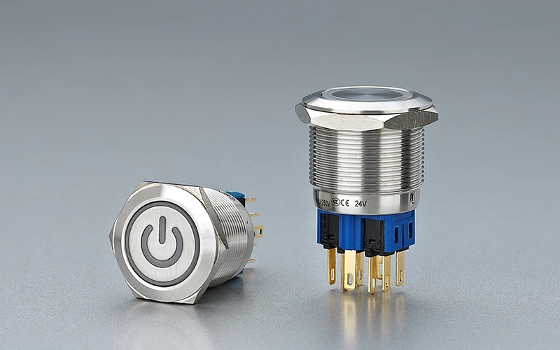
Part 1. What triple-pole means in a push-button circuit
A pole is a separate contact path. A triple-pole operator therefore gives the designer three paths that may be assigned to three NO contacts, three NC contacts, or a mixed arrangement when the selected model supports it.
| Specification term | What it tells the panel designer | What it does not tell you |
|---|---|---|
| Pole | Number of separate contact paths | The voltage or load duty |
| Throw | Whether a path changes between contacts | The physical terminal location |
| NO / NC | State before and during actuation | Whether all poles share the same rating |
| Momentary / maintained | How long the state is held | Whether a safety circuit is validated |
The actuator can move one mechanism while the electrical design treats the three poles as separate circuits. That makes the contact schedule more important than the marketing label.
Part 2. How to map three poles before wiring
Start with a pole-by-pole terminal schedule rather than a single “three-pole” note. Give every contact path an identifier such as P1, P2, and P3, then record its normal state, destination, wire reference, and test condition.
| Pole | Normal state | Actuated state | Destination | RFQ note |
|---|---|---|---|---|
| P1 | NO or NC | Opposite state | Command input 1 | Record terminal numbers |
| P2 | NO or NC | Opposite state | Indicator or interlock input | Confirm shared reference |
| P3 | NO or NC | Opposite state | PLC or relay input | Confirm isolation need |
This table prevents a common error: assuming that a three-pole operator has three identical contact blocks when the drawing actually needs a mixed NO/NC arrangement. It also gives purchasing a checkable terminal list.
Wskazówka: Compare the wiring schedule with the manufacturer drawing and the NO versus NC guide before releasing a panel BOM. IEC device terminology defines scope, but the selected model drawing defines the terminal map (PN-EN 60947-5-1).
Part 3. Panel and actuator checks that affect the layout
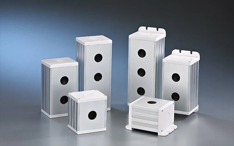
Contact topology does not remove mechanical constraints. Verify the panel cutout, body depth, terminal orientation, nut or clip engagement, and the clearance needed to bend wires without loading the terminals.
Use the push-button control-panel layout guide for the broader drilling sequence, then add these triple-pole checks:
- reserve space for three terminal paths and their labels;
- show the rear body and wire bend envelope on the drawing;
- test the operator with the intended glove and access conditions;
- separate signal wiring from higher-energy conductors where the cabinet design requires it;
- keep the pole identifiers visible in the schematic and inspection record.
Part 4. Where the control-circuit boundary stops
Triple-pole describes contact paths, not a blanket permission to switch a motor, heater, or three-phase branch. The load, utilization category, inrush, isolation method, and local safety design still control the selection.
| Application question | Dlaczego to ma znaczenie |
|---|---|
| Is this a PLC, relay, lamp, or contactor command? | A control input is different from a power path. |
| What are the steady and transient currents? | A catalogue current field may not cover the actual duty. |
| Does the function affect safety? | An emergency-stop or interlock function needs its own validated architecture. |
| Are the poles electrically independent? | Shared references can change the wiring and test plan. |
Ważne: Do not use a triple-pole button as proof that a three-phase load may be switched directly. Confirm the model’s rated duty and use a contactor or safety architecture when the circuit requires one (aparatura obwodów sterowniczych IEC 60947-5-1).
Part 5. How to use the ONPOW GQ22 family as a starting path
Ten ONPOW GQ22 metal push button category is a sensible starting route when the project needs a metal panel operator and the buyer can confirm the required contact arrangement on a specific model page or drawing. The category page is a routing point, not a substitute for a model-level electrical schedule.
Before selecting a GQ22 SKU, match:
- required pole and NO/NC arrangement;
- momentary or maintained operation;
- panel cutout and thickness;
- terminal style and rear clearance;
- contact duty for each of the three paths;
- front environmental requirement and documentation.
For broader metal construction options, review the metal push button switch line. If the drawing cannot prove the three-pole arrangement, stop at the family-review stage and ask engineering for the exact model evidence.
Part 6. What to send in the RFQ and when to stop
Send the following with the quote request through skontaktuj się z nami:
- schematic showing P1, P2, and P3;
- NO/NC state for every pole;
- momentary or maintained requirement;
- panel cutout, thickness, and rear clearance drawing;
- terminal and wire-entry preference;
- steady, transient, and load type for each circuit;
- environment, front protection target, and documentation needs;
- quantity, sample requirement, and revision-controlled drawing.
Stop and request engineering confirmation if the design assumes direct motor switching, a safety function, an unlisted pole arrangement, or a rating copied from a different model.
Najczęściej zadawane pytania
What does triple pole mean on a push button switch?
It means the operator controls three separate contact paths. The exact NO/NC arrangement and terminal numbering remain model-specific.
Is a triple-pole button the same as a three-phase power switch?
No. Three poles describe contact paths; they do not prove that the button is rated for a three-phase load or motor duty.
How many terminals should an RFQ list?
List the terminal numbers for each pole from the chosen model drawing. Do not infer the terminal count from the phrase “triple pole” alone.
Does momentary versus maintained change all poles together?
It depends on the selected mechanism. State the required actuation mode and verify the model drawing before ordering.
How much rear clearance is needed?
Enough for the body, terminal orientation, wire bend radius, and service access shown on the model drawing. A panel thickness alone is not a rear-clearance specification.
When is a contactor still required?
Use a contactor or other controlled architecture when the downstream load, inrush, isolation, or safety design exceeds the push-button contact duty.
What should I send with a triple-pole quote request?
Send the schematic, pole states, model preference, panel drawing, circuit duty, environment, quantity, and documentation requirements.



