

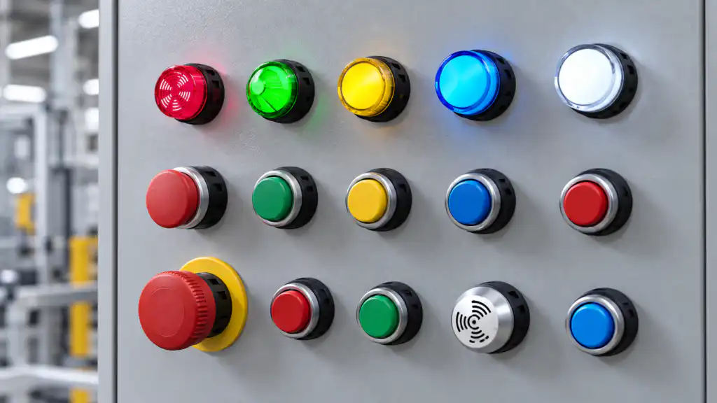
Industrial indicator light colors communicate machine status, but the meaning is not created by color alone. In a common IEC-oriented panel convention, red calls for urgent attention, amber or yellow warns of an abnormal condition, green shows a normal or satisfactory state, blue requests a specific action, and white carries neutral or general information. That is a useful starting point, not a universal wiring rule. The machine risk assessment, applicable standard, customer specification, written legend, and control sequence must agree before any lamp color is assigned.
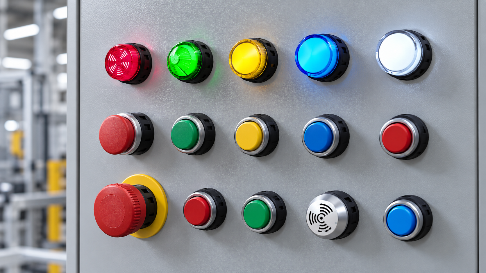
Quick reference: what each indicator light color usually means
The table below is a practical design aid for industrial control panels. It deliberately uses “common use” rather than claiming that every factory, industry, or country assigns the same state to every color.
| Kolor | Common status meaning | Typical operator interpretation | Design caution |
|---|---|---|---|
| Czerwony | Danger, emergency, serious abnormal condition | Stop, investigate, or act immediately | Do not use red for an ordinary healthy “power on” state if it could dilute an alarm convention |
| Amber or yellow | Warning, abnormal state, condition approaching a limit | Monitor, diagnose, or prepare to intervene | Define the threshold and required response; “attention” is too vague on its own |
| Zielony | Normal, safe, ready, or satisfactory condition | Operation may continue under the defined condition | “Running,” “ready,” and “safe” are different states; label the exact one |
| Niebieski | Mandatory action or a state requiring a specific operator response | Follow the stated instruction | Pair it with a label or symbol that names the required action |
| Biały | Neutral, general, confirmation, or information not assigned to another color | Read the adjacent legend for the exact state | Do not let white become a catch-all for unrelated or safety-significant states |
Ten IEC 60073 publication page describes general coding principles for visual, acoustic, and tactile indications. For machine electrical equipment, the applicable project may also reference IEC 60204-1. Always confirm the adopted edition, national implementation, customer requirements, and any industry-specific rules. A color table copied from another machine is not a substitute for that review.
Why indicator colors cannot be interpreted in isolation
An illuminated lamp answers only the question designed into its circuit. A green lamp driven by a PLC “run command” does not prove that a motor is turning. A red lamp connected to an overload contact does not identify every possible reason the machine stopped. The signal source, software logic, field feedback, and label determine the actual meaning.
Write each state as a complete statement before choosing a color. “Conveyor commanded to run,” “conveyor speed proven,” and “production permitted” rely on different evidence. A good panel legend names that evidence clearly.
Ten ONPOW indicator-light selection guide covers the wider device-selection process. Use the color decision together with voltage, cutout, terminal, lens, brightness, front protection, and environmental requirements.
Red indicator lights: reserve urgency for real urgency
Red is commonly associated with danger, emergency, or a serious abnormal condition. It should make the required response obvious. Using red for both routine conditions and critical faults weakens its priority message.
Separate an emergency-stop actuator from an indicator. A red lamp is a human-facing indication; it neither performs energy isolation nor proves that hazardous motion has ended. State whether it means “button actuated,” “safety circuit interrupted,” “reset required,” or another defined status.
Amber or yellow indicator lights: define the warning threshold
Amber or yellow usually indicates an abnormal condition that needs attention but is not necessarily an immediate danger. Examples can include a filter approaching its service limit, temperature outside a preferred band, low material level, maintenance due, or a process waiting for intervention.
Define the threshold and response. “Temperature warning at 75°C—check cooling” is actionable; “warning” alone encourages guesswork. If the condition can progress to a red alarm, document and test the transition.
Green indicator lights: distinguish normal, ready, and running
Green commonly communicates a normal or satisfactory condition. It may be assigned to “control power healthy,” “machine ready,” “cycle complete,” “guard closed,” or “motor running,” but those states are not interchangeable.
Choose the signal source that proves the state the label promises. For example, a green “motor running” indicator based only on the output command can remain lit even if a contactor fails to close. Where confirmation matters, derive the indication from appropriate feedback and account for sensor or feedback failure in the machine design.
Blue indicator lights: state the required action
Blue is often used when a specific operator action is required. That can include loading material, confirming a step, resetting after a defined condition, or following a maintenance instruction. The lamp should be next to a concise label or symbol that identifies the action.
Avoid using blue merely because it is distinctive. Include its meaning in the instructions, panel legend, training, and acceptance test.
White indicator lights: neutral information still needs a legend
White is commonly used for neutral confirmation or information that is not appropriately assigned to red, amber, green, or blue. Possible applications include power present, a selected mode, auxiliary function active, or general status.
White does not mean “anything else.” Group related functions, use consistent wording, and place each lamp near the control or equipment it describes.
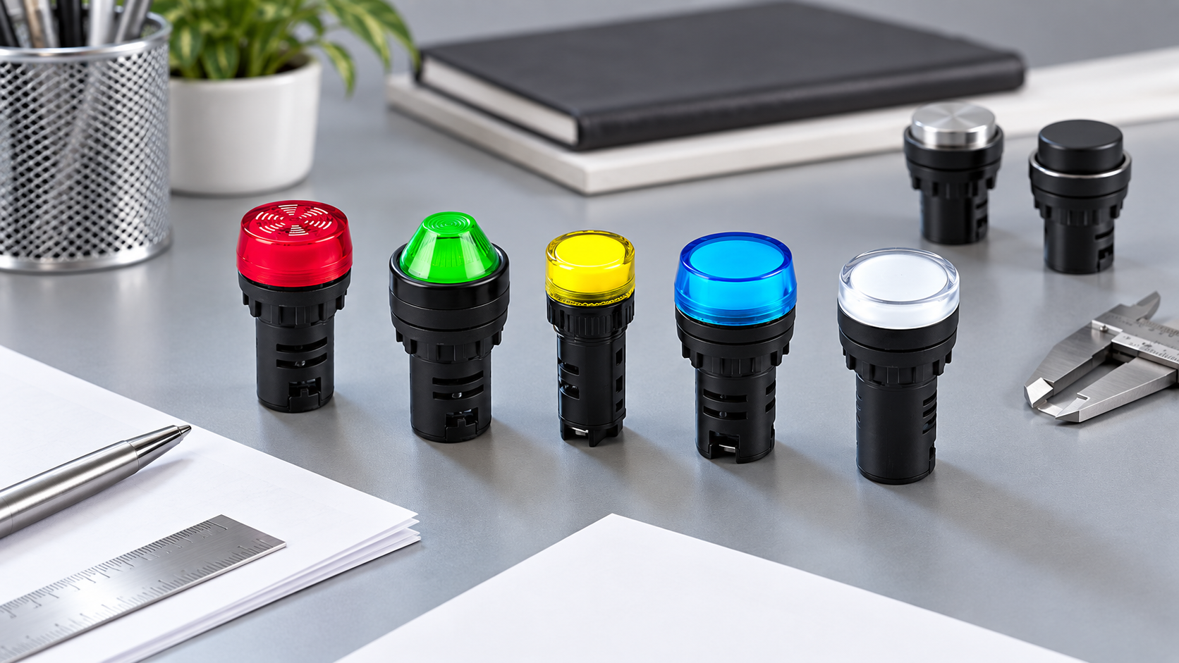
Ten ONPOW AD16 series shows a family of compact panel signal lamps in multiple lens colors. Product appearance helps identify a family, but the exact order code, electrical rating, terminal arrangement, mounting dimensions, and available colors must be confirmed from current product documentation before ordering. The broader ONPOW signal-lamp range provides another starting point for product selection.
Do not rely on color alone
Color perception varies, lighting changes apparent color, and operators view panels from different angles. Red and green can also be difficult for some users to distinguish. The W3C’s guidance on use of color reinforces a useful human-factors principle: provide information in addition to color.
For a machine panel, useful redundant cues include:
- a short, unambiguous text label beside each lamp;
- a standardized graphical symbol where appropriate;
- consistent physical position and grouping;
- steady versus flashing behavior that is deliberately defined;
- an HMI message or alarm code that names the condition;
- an audible signal where the risk assessment requires one;
- a documented response in operating and maintenance instructions.
Use enough redundancy that misreading one cue does not leave the operator guessing about an important state.
Steady and flashing indications
A flashing light normally attracts more attention than a steady light, so use it sparingly. Define the trigger, flash rate, acknowledgment behavior, and transition to steady or off. Check whether two flashing conditions can occur together and whether reflections from other equipment could create confusion.
Do not assume every LED indicator contains a flasher. Some applications flash through control logic; others require a purpose-built device. Confirm the exact specification, document the pattern, and test it with the alarm condition.
Panel layout, visibility, and ambient light
Place high-priority indications within the expected field of view and keep their labels readable from the normal operating position. Avoid glare from glossy doors, sunlight through windows, bright task lighting, and reflections from illuminated push buttons. The push-button control-panel layout guide explains how spacing and grouping help operators connect a signal with the correct control.

Check the complete panel under real lighting. Evaluate viewing distance, angle, lens size, contrast, glare, and whether operators wear tinted eye protection.
A practical color-assignment workflow
- List every state the operator must see, including normal operation, warnings, faults, required actions, maintenance states, and loss of power.
- Identify the evidence for each state: command, auxiliary contact, sensor, safety output, communications value, or calculated condition.
- Rank the required response by urgency and consequence.
- Review the applicable standard, national adoption, customer specification, and industry rules.
- Assign color, label, symbol, position, and steady or flashing behavior as one coordinated interface.
- Check that no two nearby indications communicate conflicting meanings.
- Review the scheme with operators, maintenance staff, controls engineers, and the responsible safety specialist.
- Test every state, including relevant failure and reset behavior.
- Update schematics, software descriptions, manuals, spare lists, and the panel legend before release.
This workflow prevents selecting a lamp color before the machine-state definition is approved.
Common mistakes to avoid
Copying colors from a different machine
The other machine may follow a different standard, customer convention, risk assessment, or control philosophy. Reuse only after a documented review.
Using green to prove a condition it does not measure
A green command lamp can be useful, but its label must not claim verified motion, pressure, temperature, or safety if the circuit does not monitor that result.
Turning every abnormal state red
If minor service reminders and urgent hazards look identical, operators lose the priority information that color is meant to provide.
Omitting labels because the colors seem obvious
Color meanings are contextual. Labels, symbols, alarm messages, and documentation make the intended state explicit.
Choosing the lens before the electrical variant
The correct color does not compensate for an incorrect voltage, waveform, polarity, terminal, cutout, or environmental rating. Compare the full order code and datasheet.
RFQ checklist for colored indicator lights
Send the supplier and panel builder:
- the exact state and written legend for each color;
- the applicable standard, customer convention, and required documentation;
- steady or flashing behavior and how it is controlled;
- AC or DC supply, rated voltage range, frequency, polarity, and current limits;
- panel cutout, thickness, rear clearance, terminal style, and wire range;
- viewing distance, ambient light, lens size, and brightness requirements;
- temperature, vibration, cleaning, dust, moisture, and front-protection requirements;
- required product markings, samples, spare quantities, and acceptance tests.
Ask ONPOW to confirm the available variant and current documentation through the contact page rather than inferring specifications from a photograph.
Film edukacyjny
This short neutral video from Venngage explains why color blindness matters in visual communication. It supports the recommendation to pair panel colors with labels, symbols, position, or other cues; it is not a machine-safety standard or an ONPOW product instruction.
Często zadawane pytania
Does red always mean the machine is stopped?
No. Red commonly signals danger or a serious abnormal state, but the circuit and label determine what it proves. A stopped machine can also be in a normal planned state.
Can green mean both ready and running?
One project may use green for either state, but a single lamp should have one clear meaning. If both states matter, provide separate, clearly labeled indications or an appropriate status display.
Is amber the same as an alarm?
Amber often identifies a warning or abnormal condition requiring attention. Define the threshold, urgency, and required response instead of relying on the word “alarm” alone.
What is a blue indicator light used for?
Blue is commonly associated with a specific required action. Pair it with a label or symbol that tells the operator what action to take.
Can color replace a text label on a control panel?
It should not. A label or symbol provides a second cue, reduces ambiguity, and supports users who cannot reliably distinguish every color.
Final recommendation
Use red, amber, green, blue, and white as part of a documented signaling system—not as isolated decoration. Define the machine state first, identify the evidence behind it, confirm the applicable standard and project convention, then coordinate color with labels, symbols, position, and behavior. Finally, verify the real panel with operators under normal and fault conditions before release.
Sources for verification: IEC 60073 coding principles; IEC 60204-1 machine electrical equipment; W3C Understanding Use of Color; ONPOW AD16 series.
Customization
ONPOW undertakes a variety of custom needs for push-button development. Confirm whether packaging, marking or documentation OEM/ODM applies to Red, Green, Amber, Blue and White Indicator Light Meanings in the quotation.
Minimum order quantity, lead time and trade terms are not published here; confirm them with sales at sales@onpow.com.



