

A micro switch works by using a small actuator movement to release a spring-loaded snap mechanism that changes the electrical contacts quickly. The contact change occurs at a defined operating point rather than following the actuator slowly through its full travel. This behavior helps create repeatable switching in compact mechanisms. A typical changeover unit provides common (COM), normally closed (NC), and normally open (NO) terminals, but the exact circuit, rating, force, travel, and environmental protection depend on the selected model. Treat the switch as a sensing component, not as a complete safety function, and verify the machine circuit before installation.
Krótka odpowiedź: Wybór jest decyzją systemową. Należy wspólnie potwierdzić interfejs mechaniczny, interfejs elektryczny, środowisko, reakcję człowieka, plan konserwacji oraz obowiązujące normy. Poniższe przykłady stanowią wskazówki decydujące, a nie uniwersalne oceny produktów.
Jak działa urządzenie lub system
Inside the device, the external plunger or lever stores force in a spring or moving blade. Once the mechanism crosses its operating point, the stored energy transfers the moving contact rapidly from one fixed contact to the other. Releasing the actuator crosses a separate release point and the mechanism snaps back. The difference between operating and release position is intentional differential travel; it reduces unstable chatter near the change point. The mechanism can feel simple, but actuator geometry, contact material, load type, contamination, vibration, and overtravel all affect service behavior.

Kryteria wyboru w skrócie
| Obszar decyzyjny | Co zweryfikować | Dlaczego to ma znaczenie |
|---|---|---|
| Actuator | Match plunger, hinge lever, roller lever, or other form to the machine motion | The actuator determines approach direction, available travel, and mechanical leverage. |
| Operating force | Confirm the force range in the chosen datasheet | Too little force may miss the operating point; excessive force can damage the mechanism. |
| Pretravel and overtravel | Provide enough motion to operate reliably without using the switch as a hard stop | Controlled overtravel accommodates tolerance while protecting the internal snap mechanism. |
| Contact form | Map COM, NO, and NC to the required control logic | Terminal labels describe the de-energized mechanical state, not the desired machine behavior. |
| Obciążenie elektryczne | Check voltage, current, AC/DC type, inrush, and minimum load | A rating for one load category cannot automatically be applied to another. |
| Środowisko | Evaluate dust, moisture, oil, temperature, shock, and vibration | An exposed basic switch and a sealed assembly solve different environmental problems. |
| Montaż | Control hole position, fastener torque, alignment, and actuator approach | Misalignment changes effective force and travel and can shorten life. |
| Weryfikacja | Test the complete mechanism at tolerance extremes | A bench click alone does not prove reliable operation in the assembled machine. |
Tabela ma charakter celowo jakościowy. Limity numeryczne muszą pochodzić z aktualnej karty katalogowej dla konkretnego modelu oraz z warunków projektowych maszyny. Nie należy przenosić wartości z podobnie wyglądającego produktu, innego napięcia, innej kategorii obciążenia ani ze strony konkurencji.
Jak dokonać wyboru
Actuator
Match plunger, hinge lever, roller lever, or other form to the machine motion This matters because the actuator determines approach direction, available travel, and mechanical leverage. Record the chosen value, the source document, and the condition under which it applies. If the requirement cannot be verified from the current product documentation, keep it open for supplier confirmation rather than filling the gap with an assumption.
Operating force
Confirm the force range in the chosen datasheet This matters because too little force may miss the operating point; excessive force can damage the mechanism. Record the chosen value, the source document, and the condition under which it applies. If the requirement cannot be verified from the current product documentation, keep it open for supplier confirmation rather than filling the gap with an assumption.
Pretravel and overtravel
Provide enough motion to operate reliably without using the switch as a hard stop This matters because controlled overtravel accommodates tolerance while protecting the internal snap mechanism. Record the chosen value, the source document, and the condition under which it applies. If the requirement cannot be verified from the current product documentation, keep it open for supplier confirmation rather than filling the gap with an assumption.
Contact form
Map COM, NO, and NC to the required control logic This matters because terminal labels describe the de-energized mechanical state, not the desired machine behavior. Record the chosen value, the source document, and the condition under which it applies. If the requirement cannot be verified from the current product documentation, keep it open for supplier confirmation rather than filling the gap with an assumption.
Obciążenie elektryczne
Check voltage, current, AC/DC type, inrush, and minimum load This matters because a rating for one load category cannot automatically be applied to another. Record the chosen value, the source document, and the condition under which it applies. If the requirement cannot be verified from the current product documentation, keep it open for supplier confirmation rather than filling the gap with an assumption.
Środowisko
Evaluate dust, moisture, oil, temperature, shock, and vibration This matters because an exposed basic switch and a sealed assembly solve different environmental problems. Record the chosen value, the source document, and the condition under which it applies. If the requirement cannot be verified from the current product documentation, keep it open for supplier confirmation rather than filling the gap with an assumption.
Montaż
Control hole position, fastener torque, alignment, and actuator approach This matters because misalignment changes effective force and travel and can shorten life. Record the chosen value, the source document, and the condition under which it applies. If the requirement cannot be verified from the current product documentation, keep it open for supplier confirmation rather than filling the gap with an assumption.
Weryfikacja
Test the complete mechanism at tolerance extremes This matters because a bench click alone does not prove reliable operation in the assembled machine. Record the chosen value, the source document, and the condition under which it applies. If the requirement cannot be verified from the current product documentation, keep it open for supplier confirmation rather than filling the gap with an assumption.

Przegląd aplikacji
Wykorzystaj poniższe scenariusze jako wytyczne do przeglądu inżynieryjnego. Same w sobie nie potwierdzają one przydatności:
- Door or guard position feedback where a moving part provides a controlled stroke. During commissioning, verify the command, expected response, abnormal response, and reset behavior in the assembled machine.
- Home-position or end-position detection inside compact equipment. During commissioning, verify the command, expected response, abnormal response, and reset behavior in the assembled machine.
- Presence detection in vending, appliance, and handling mechanisms. During commissioning, verify the command, expected response, abnormal response, and reset behavior in the assembled machine.
- Interlock input in a control circuit after the risk assessment defines the required architecture. During commissioning, verify the command, expected response, abnormal response, and reset behavior in the assembled machine.
- Counting or sequencing tasks where a cam repeatedly drives the actuator. During commissioning, verify the command, expected response, abnormal response, and reset behavior in the assembled machine.
Dla każdego przypadku należy uwzględnić skrajne tolerancje, rozruch, wyłączenie, utratę zasilania, przywrócenie zasilania, tryb konserwacji, przewidywalne niewłaściwe użycie oraz wymianę komponentów. W przypadkach, gdy polecenie wpływa na bezpieczeństwo personelu, funkcja bezpieczeństwa musi być zaprojektowana i zwieziona niezależnie od zwykłego sterowania procesem.
Uruchomienie i weryfikacja
- Zablokuj wymaganie. Opisz zamierzony stan, działanie operatora, obciążenie, zasilanie, środowisko i czas reakcji prostym językiem.
- Sprawdź dokładny model. Dopasuj kod zamówienia do jego aktualnego rysunku, tabeli znamionowej, schematu wyprowadzeń i instrukcji.
- Sprawdź instalację. Potwierdzić wycięcie, elementy złączne, osiowanie, wpust kablowy, prześwit z tyłu, odciążenie naciągu oraz zabezpieczenie części pod napięciem.
- Test normalnego działania. Przeprowadź ćwiczenia z urządzeniem w całym oczekiwanym zakresie ruchu, przez użytkowników, z różnymi obciążeniami oraz w warunkach środowiskowych.
- Przetestuj nienormalne warunki. Uwzględnij odłączony przewód, zablokowany mechanizm, brak zasilania, zanieczyszczenie oraz inne usterki zidentyfikowane w ocenie ryzyka.
- Zapisz wyniki. Zachowaj model, wersję, metodę testową, datę, kryteria akceptacji, zarejestrowane obserwacje oraz osobę zatwierdzającą.
- Zaplanuj okresowe kontrole. Częstotliwość przeglądów i wymian należy opierać na warunkach pracy, otoczeniu, krytyczności i zaobserwowanym zużyciu, a nie na wymyślonym, uniwersalnym harmonogramie.
Częste błędy przy rekrutacji
- Using the audible click as proof that the electrical contacts changed. Zapobiegnij temu poprzez wyznaczenie właściciela, zarejestrowanie odpowiedniego rysunku technicznego lub karty katalogowej oraz przetestowanie faktycznej instalacji zamiast polegania na nazwie produktu lub zdjęciu z katalogu.
- Allowing a cam to strike the lever sideways or at excessive speed. Zapobiegnij temu poprzez wyznaczenie właściciela, zarejestrowanie odpowiedniego rysunku technicznego lub karty katalogowej oraz przetestowanie faktycznej instalacji zamiast polegania na nazwie produktu lub zdjęciu z katalogu.
- Switching an inductive or high-inrush load from a resistive-load rating. Zapobiegnij temu poprzez wyznaczenie właściciela, zarejestrowanie odpowiedniego rysunku technicznego lub karty katalogowej oraz przetestowanie faktycznej instalacji zamiast polegania na nazwie produktu lub zdjęciu z katalogu.
- Assuming every three-terminal layout uses the same physical pin order. Zapobiegnij temu poprzez wyznaczenie właściciela, zarejestrowanie odpowiedniego rysunku technicznego lub karty katalogowej oraz przetestowanie faktycznej instalacji zamiast polegania na nazwie produktu lub zdjęciu z katalogu.
- Leaving an unsealed switch exposed to washdown, chips, oil, or condensation. Zapobiegnij temu poprzez wyznaczenie właściciela, zarejestrowanie odpowiedniego rysunku technicznego lub karty katalogowej oraz przetestowanie faktycznej instalacji zamiast polegania na nazwie produktu lub zdjęciu z katalogu.
- Treating one basic switch as a complete safety-rated guard-monitoring system. Zapobiegnij temu poprzez wyznaczenie właściciela, zarejestrowanie odpowiedniego rysunku technicznego lub karty katalogowej oraz przetestowanie faktycznej instalacji zamiast polegania na nazwie produktu lub zdjęciu z katalogu.
Co uwzględnić w zapytaniu ofertowym do dostawcy
Przydatne zapytanie powinno określać zastosowanie, rynek docelowy, obowiązujące normy, szczegóły dotyczące zasilania i obciążenia, interfejs sterowania, rysunek mechaniczny, wymiary panelu lub montażowe, metodę okablowania, środowisko, oczekiwaną częstotliwość pracy, ilość oraz wymaganą dokumentację. Należy dodać fotografie lub szkic ruchu, gdy sposób działania siłownika lub obsługi przez operatora jest trudny do opisania. Poproś dostawcę o wskazanie przyjętych założeń i odstępstw. W przypadku nowego lub zmodyfikowanego projektu należy pozyskać próbki i przeprowadzić pełną walidację przed złożeniem zamówienia wielkoseryjnego.
ONPOW zapewnia ONPOW micro switch products w szerszym kontekście asortyment produktów sterowania przemysłowego. Skorzystaj ze stron produktów, aby zidentyfikować kandydackie rodziny, a następnie potwierdź dokładny model na podstawie aktualnych informacji technicznych oraz warunków swojego projektu.
Powiązane materiały ONPOW
Autorytatywne źródła
- urządzenia w obwodach sterowniczych zgodne z normą IEC 60947-5-1
- Wymagania OSHA dotyczące osłon maszyn
Film edukacyjny
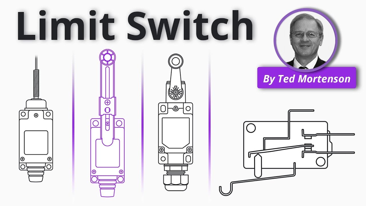
Further learning: Limit Switch Explained | Working Principles by RealPars. The video explains the underlying concept; the project must still follow its own risk assessment and manufacturer documentation.
Często zadawane pytania
Dlaczego nazywa się to mikroprzełącznikiem?
Termin ten zazwyczaj opisuje kompaktowy, czuły przełącznik szybkodziałający. Nie gwarantuje on jednego uniwersalnego rozmiaru, siły, parametru znamionowego ani układu wyprowadzeń.
Czym są COM, NO i NC?
COM to połączenie zestyku ruchomego. NC jest połączony z COM w normalnym stanie mechanicznym; NO zostaje połączony po zadziałaniu. Sprawdź na schemacie dla konkretnego modelu.
Czy mikroprzełącznik potrzebuje zasilania?
Podstawowy mikroprzełącznik elektromechaniczny jest stykiem bezpotencjałowym i nie wymaga zasilania do poruszania swoich styków, chociaż monitorowany obwód zapewnia sygnał elektryczny.
Czy mikroprzełącznik może bezpośrednio sterować silnikiem?
Tylko wtedy, gdy dokładne obciążenie mieści się w deklarowanej przez producenta klasie i kategorii. Przekaźniki sterujące lub styczniki są często używane do większych obciążeń lub obciążeń o dużym prądzie włączeniowym.
Jak należy to przetestować?
Sprawdź ciągłość na zaciskach, a następnie zweryfikuj punkty zadziałania i zwolnienia, ustawienie, nadskok, narażenia środowiskowe oraz zachowanie w kompletnym obwodzie sterowania.
Ostateczna reguła wyboru
Wybierz komponent tylko wtedy, gdy jego udokumentowane granice mechaniczne, elektryczne, środowiskowe, użyteczności i utrzymaniowe mieszczą się w całości w zmontowanym systemie. Jeśli jedna granica pozostaje nieznana, potraktuj ją jako otwarte pytanie inżynieryjne. Krótkie opóźnienie walidacji jest mniej kosztowne niż projektowanie wokół założenia, które pojawia się dopiero po instalacji.



