

Industrial micro switch selection requires separate mechanical, electrical, environmental, and installation checks. Begin carefully with the machine movement: direction, speed, available force, operating point, overtravel, and reset margin. Then define the real electrical load, including AC or DC operation, inrush, minimum current, switching frequency, and control input behavior. Finally, check package size, terminals, sealing, temperature, vibration, mounting, documentation, and maintenance access. A familiar body shape or headline current rating is not enough to prove that a switch fits the application.
Zasada wyboru: Traktuj urządzenie, siłownik, styki, obudowę, okablowanie, logikę sterowania, użytkownika oraz ruch maszyny jako jeden system. Przykłady produktów ilustrują jedynie formę; ostateczna przydatność musi wynikać z aktualnej dokumentacji dla konkretnego kodu zamówienia oraz z walidacji w gotowym urządzeniu.
Jak działa ten mechanizm
Most industrial micro switches use a snap-action mechanism that transfers slowly applied actuator force into a rapid contact change. This helps repeatability and reduces the time contacts spend between states. The external actuator and internal mechanism form one mechanical chain. Contact material and geometry form a separate electrical boundary. Both boundaries must be satisfied at the same time, and the complete machine must be tested under realistic tolerances.

Kryteria wyboru w skrócie
| Obszar decyzyjny | Co zweryfikować | Powód inżynieryjny |
|---|---|---|
| Actuator | Match plunger, lever, or roller to the target motion | Geometry determines force, reach, speed, and wear. |
| Operating force | Confirm the available force at worst-case alignment | Insufficient force causes missed operation; excessive force damages parts. |
| Travel | Check pretravel, operating point, overtravel, and release travel | The target must operate and reset reliably without bottoming out. |
| Contact form | Map COM, NO, and NC to the required state logic | Terminal position must come from the exact diagram. |
| Załaduj | Define voltage, current, AC/DC type, inrush, and minimum load | A resistive rating cannot be applied blindly to another load. |
| Frequency and life | Estimate realistic operations and switching duty | Mechanical and electrical life are different limits. |
| Środowisko | Check dust, moisture, oil, temperature, shock, and vibration | The installation may require a sealed assembly or enclosure. |
| Mounting and terminals | Verify holes, torque, clearances, terminal style, and strain relief | Integration errors can dominate switch performance. |
Ta tabela ma charakter celowo jakościowy. Limity numeryczne, parametry znamionowe, moment obrotowy, siła, przemieszczenie, deklaracje środowiskowe i wartości wytrzymałościowe należy pobrać z aktualnego arkusza danych i ocenić w warunkach aplikacji.
Szczegółowy proces selekcji
Actuator
Co zweryfikować: Match plunger, lever, or roller to the target motion. Geometry determines force, reach, speed, and wear. The requirement should be written in the project specification and traced to the exact model drawing or datasheet. Review worst-case tolerance, wear, contamination, maintenance access, and foreseeable misuse. If the available documentation does not define the boundary, keep the point open for supplier confirmation and sample testing rather than substituting an assumption.
Operating force
Co zweryfikować: Confirm the available force at worst-case alignment. Insufficient force causes missed operation; excessive force damages parts. The requirement should be written in the project specification and traced to the exact model drawing or datasheet. Review worst-case tolerance, wear, contamination, maintenance access, and foreseeable misuse. If the available documentation does not define the boundary, keep the point open for supplier confirmation and sample testing rather than substituting an assumption.
Travel
Co zweryfikować: Check pretravel, operating point, overtravel, and release travel. The target must operate and reset reliably without bottoming out. The requirement should be written in the project specification and traced to the exact model drawing or datasheet. Review worst-case tolerance, wear, contamination, maintenance access, and foreseeable misuse. If the available documentation does not define the boundary, keep the point open for supplier confirmation and sample testing rather than substituting an assumption.
Contact form
Co zweryfikować: Map COM, NO, and NC to the required state logic. Terminal position must come from the exact diagram. The requirement should be written in the project specification and traced to the exact model drawing or datasheet. Review worst-case tolerance, wear, contamination, maintenance access, and foreseeable misuse. If the available documentation does not define the boundary, keep the point open for supplier confirmation and sample testing rather than substituting an assumption.
Załaduj
Co zweryfikować: Define voltage, current, AC/DC type, inrush, and minimum load. A resistive rating cannot be applied blindly to another load. The requirement should be written in the project specification and traced to the exact model drawing or datasheet. Review worst-case tolerance, wear, contamination, maintenance access, and foreseeable misuse. If the available documentation does not define the boundary, keep the point open for supplier confirmation and sample testing rather than substituting an assumption.
Frequency and life
Co zweryfikować: Estimate realistic operations and switching duty. Mechanical and electrical life are different limits. The requirement should be written in the project specification and traced to the exact model drawing or datasheet. Review worst-case tolerance, wear, contamination, maintenance access, and foreseeable misuse. If the available documentation does not define the boundary, keep the point open for supplier confirmation and sample testing rather than substituting an assumption.
Środowisko
Co zweryfikować: Check dust, moisture, oil, temperature, shock, and vibration. The installation may require a sealed assembly or enclosure. The requirement should be written in the project specification and traced to the exact model drawing or datasheet. Review worst-case tolerance, wear, contamination, maintenance access, and foreseeable misuse. If the available documentation does not define the boundary, keep the point open for supplier confirmation and sample testing rather than substituting an assumption.
Mounting and terminals
Co zweryfikować: Verify holes, torque, clearances, terminal style, and strain relief. Integration errors can dominate switch performance. The requirement should be written in the project specification and traced to the exact model drawing or datasheet. Review worst-case tolerance, wear, contamination, maintenance access, and foreseeable misuse. If the available documentation does not define the boundary, keep the point open for supplier confirmation and sample testing rather than substituting an assumption.

Przegląd aplikacji
- Compact position detection. Record the expected command, response, release behavior, abnormal condition, and acceptance evidence for the assembled machine.
- Presence sensing inside equipment. Record the expected command, response, release behavior, abnormal condition, and acceptance evidence for the assembled machine.
- Cam sequencing. Record the expected command, response, release behavior, abnormal condition, and acceptance evidence for the assembled machine.
- Door-position feedback after risk assessment. Record the expected command, response, release behavior, abnormal condition, and acceptance evidence for the assembled machine.
- Counting and indexing with controlled motion. Record the expected command, response, release behavior, abnormal condition, and acceptance evidence for the assembled machine.
Dla każdego zastosowania należy uwzględnić rozruch, normalną pracę, wyłączenie, zanik zasilania, przywrócenie zasilania, tryb konserwacji, wymianę komponentów oraz uszkodzenia zidentyfikowane w ocenie ryzyka. Ogólny wyłącznik sterujący nie powinien być traktowany jako kompletna funkcja bezpieczeństwa.
Lista kontrolna odbioru technicznego
- Zablokuj wymaganie. Określ zamierzoną czynność, warunek normalny, zasilanie, obciążenie, ruch, środowisko oraz użytkownika.
- Dopasuj kod zamówienia. Porównaj dostarczoną część z zatwierdzonym rysunkiem, schematem styków, siłownikiem, stylem zacisków i akcesoriami.
- Sprawdź instalację. Sprawdź osiowanie, elementy złączne, luz z tyłu, prowadzenie kabli, odciążenie naciągu, ochronę części pod napięciem oraz dostęp serwisowy.
- Przetestuj każdy stan. Sprawdzić działanie i zwolnienie przy skrajnych tolerancjach, oczekiwanych prędkościach, obciążeniach, w rękawicach, przy obecności zanieczyszczeń oraz w warunkach środowiskowych.
- Przetestuj nienormalne warunki. Uwzględnij odłączone przewody, zablokowane lub uszkodzone mechanizmy, utratę zasilania, zanieczyszczenia oraz inne wiarygodne uszkodzenia.
- Zarejestruj wynik. Zapisz model, wersję, metodę testową, obserwacje, kryteria akceptacji, datę i osobę zatwierdzającą.
Częste błędy
- Selecting by dimensions alone. Zapobiegnij temu, przypisując sprawdzenie do rysunku, arkusza danych, rejestru okablowania lub testu uruchomieniowego z podanym kryterium akceptacji.
- Using the audible click as electrical proof. Zapobiegnij temu, przypisując sprawdzenie do rysunku, arkusza danych, rejestru okablowania lub testu uruchomieniowego z podanym kryterium akceptacji.
- Applying a resistive rating to an inductive load. Zapobiegnij temu, przypisując sprawdzenie do rysunku, arkusza danych, rejestru okablowania lub testu uruchomieniowego z podanym kryterium akceptacji.
- Letting the target use the switch as a stop. Zapobiegnij temu, przypisując sprawdzenie do rysunku, arkusza danych, rejestru okablowania lub testu uruchomieniowego z podanym kryterium akceptacji.
- Assuming all three-terminal pinouts match. Zapobiegnij temu, przypisując sprawdzenie do rysunku, arkusza danych, rejestru okablowania lub testu uruchomieniowego z podanym kryterium akceptacji.
Co uwzględnić w zapytaniu ofertowym (RFQ)
Podaj zastosowanie, rynek docelowy, obowiązujące normy, funkcję maszyny, zasilanie i obciążenie, interfejs sterowania, logikę styków, rysunek mechaniczny, tor ruchu, wymiary panelu, metodę okablowania, środowisko, częstotliwość pracy, ilość, zapotrzebowanie na dokumentację oraz plan walidacji próbek. Poproś dostawcę o wskazanie założeń i wyłączeń. ONPOW oferuje powiązane produkty w swoim rodzina produktów dedykowana do konkretnych zastosowań i szerszy kontekst asortyment produktów sterowania przemysłowego.
Powiązane poradniki ONPOW
- Jak działa mikroprzełącznik
- Mikrostycznik a wyłącznik krańcowy
- Życie mechaniczne kontra życie elektryczne
Autorytatywne źródła
- urządzenia w obwodach sterowniczych zgodne z normą IEC 60947-5-1
- IEC 60529 Stopnie ochrony zapewniane przez obudowy
- Wymagania OSHA dotyczące osłon maszyn
- Wymagania bezpieczeństwa elektrycznego OSHA
Film edukacyjny
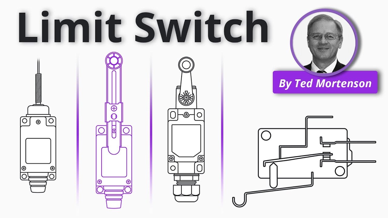
Wyjaśnienie łącznika krańcowego od RealPars stanowi ogólne tło. Decyzje projektowe nadal wymagają zastosowania obowiązujących norm i dokumentacji produktu.
Często zadawane pytania
What is the first selection step?
Document the machine motion and required operating state before comparing catalog models.
What do COM, NO, and NC mean?
They identify the moving contact and its normal mechanical connections; verify the exact terminal diagram.
Can a micro switch switch a motor directly?
Only if the exact load and inrush fall within the stated rating and category; larger loads often need an interface device.
How should samples be approved?
Test the exact order code in the complete mechanism at tolerance, load, and environmental extremes.
Ostateczna decyzja
Zatwierdź komponent tylko wtedy, gdy udokumentowane granice mechaniczne, elektryczne, środowiskowe, użyteczności, instalacji i konserwacji w pełni pasują do zmontowanego systemu. Rozstrzygnij kwestie niewiadome za pomocą aktualnych informacji od producenta i testów przed dopuszczeniem do produkcji.



