

Momentary Piezo Switches for Sealed Control Panels
A momentary piezo switch is selected for a short command or pulse, not because every piezo actuator has the same output or remains active for as long as it is pressed. Before specifying one for a sealed control panel, confirm what the controller sees: a contact change, an electronic output, or a pulse interpreted by downstream logic. Then check the exact model’s electrical rating, mounting dimensions, and manufacturer-stated front-panel protection. A rated protection level is not a guarantee that the finished enclosure is suitable for every washdown or outdoor condition. This guide focuses on the momentary decision, panel fit, circuit interface, and the checks to include in a supplier inquiry. The ONPOW PS223Z10YRD1/D page is one model example, not a substitute for the drawing and datasheet of the selected variant.
What momentary means in a piezo control
In ordinary switch language, a momentary operator returns to its normal mechanical position after the user releases it. The circuit behavior still depends on the exact switch design and its output. Piezoelectric switches often generate a brief electrical signal when the actuator is pressed; the receiving controller may capture that event, filter it, or store a state after the button is released. That stored state is a function of the controller or circuit, not proof that the front actuator itself is mechanically latching.
This distinction matters on a panel. A jog, acknowledge, reset, or request input may be intended as a momentary command. A maintained mode or power state may need a different operator, an explicit electronic latch, or a control-system state. Do not infer the behavior from a flat actuator, the LED ring, the color, or the family name. Ask the manufacturer which model variant is momentary and what the output waveform or contact state means under the specified load.
The video below shows the general difference between momentary and latching switch behavior. It is not an ONPOW-specific model demonstration; use the product drawing and controller documentation to confirm the actual interface.
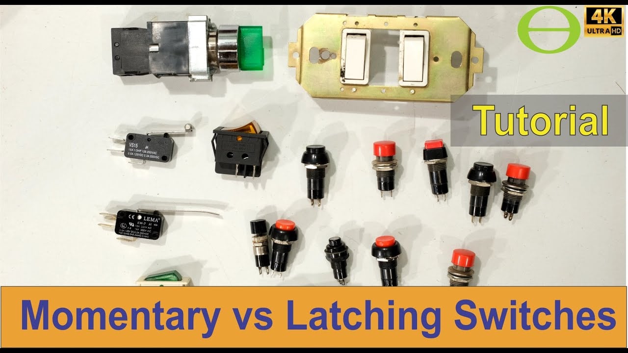
Open the momentary and latching switch explanation on YouTube
Confirm the signal interface before choosing the switch
Do not treat all piezo switches as simple dry-contact push buttons. The product drawing may describe a contact, an electronic switching output, a pulse, an illuminated actuator, or a specific wiring arrangement. A controller input that expects a contact closure may not be compatible with an output that requires a supply or has a defined polarity. Likewise, a switch’s rating should not be confused with the voltage or current that a PLC input draws.
When the output type is unclear, stop at the specification stage and ask the supplier for the terminal diagram, output description, rated supply, permissible load, and whether the output is momentary or maintained. Then check the receiving device’s input type and electrical limits. Do not devise a connection from a generic diagram for another model.
| Selection item | What to confirm | Why it matters |
|---|---|---|
| Operating action | Momentary behavior, pulse duration if specified, or maintained/latching behavior | Defines whether the signal is a command event or a persistent state |
| Output interface | Contact type or electronic output; terminal diagram and polarity if applicable | Determines whether it can connect to the intended PLC, relay, or controller input |
| Electrical rating | Rated voltage and current for the exact part number | Prevents substituting a family-level label for an actual operating limit |
| Controller input | Input voltage range, sink/source arrangement, and required current | Confirms that the switch signal can be recognized without overloading either device |
| Indication | Whether an LED is present, its supply, and whether it is independent of the switch output | Prevents assuming that a lit ring indicates the switched state |
| Environmental fit | Manufacturer’s stated front-panel protection and installation conditions | A product rating does not qualify the complete panel or installation by itself |
Treat panel sealing as an assembly question
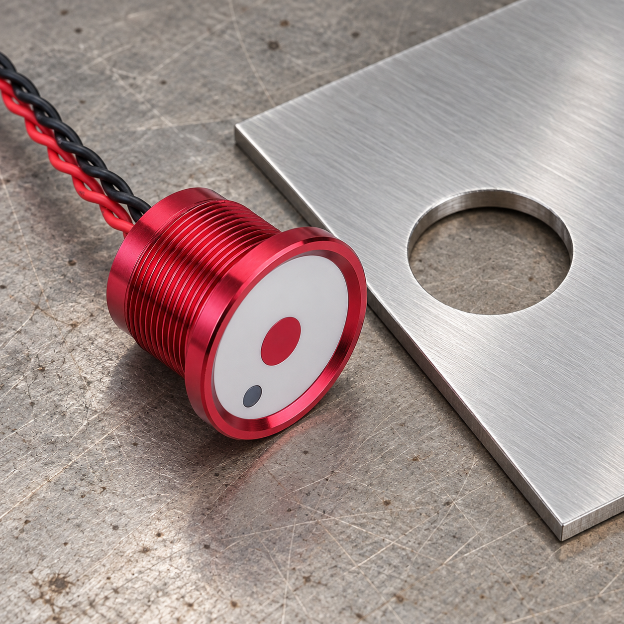
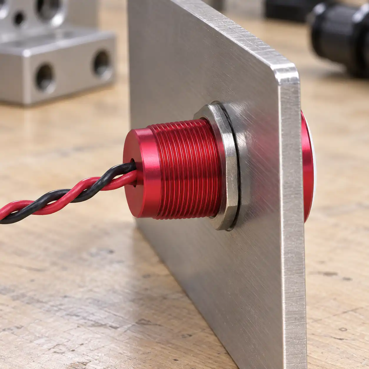
A piezo switch may be chosen for a control panel that needs a smooth, easy-to-clean front surface or an elevated enclosure rating. The front interface is only one part of the assembly. Check the specified cutout, panel thickness, mounting nut or hardware, gasket placement, surface flatness, and any cable or terminal protection behind the panel. A wrong hole size, damaged seal, uneven surface, or unsuitable enclosure can defeat the expected protection.
IEC 60529 classifies degrees of protection provided by electrical enclosures. It does not certify that every panel containing a product with an IP claim will meet the same rating after installation. Match the chosen model, enclosure, mounting procedure, and exposure conditions. If a machine needs a tested washdown or outdoor design, specify the complete assembly and have the responsible engineer verify it. Do not equate “sealed,” “waterproof,” or a high IP number with automatic suitability for rain, sun, condensation, chemicals, or field installation.
The ONPOW product page lists the PS223Z10YRD1/D with a 24 V / 200 mA switch rating, an operation-pressure range of about 5–10 N, a stated electrical life of at least 50 million cycles, and front-panel protection of IP68/IP69K. These are the manufacturer’s published values for that part page. They do not establish the rating of a finished panel or every PS-series model. Confirm the current controlled drawing, part suffix, conditions, and test scope with ONPOW before making them a procurement requirement.
Decide how the control system will use the pulse
A momentary switch can trigger a controller event even when the machine remains in a new state after the press. For example, software or a hardware latch may record that an operator acknowledged a message. That requires control logic with defined reset conditions and, where applicable, safe behavior after power loss. The operator itself does not necessarily retain the state.
The Texas Instruments momentary-switch tutorial shows one logic example where a momentary input toggles a downstream state. It explains how a short command and a stored output differ; it is not an industrial safety-circuit design or a piezo switch wiring diagram.
Before a design is released, agree whether a press is interpreted as a pulse, a held condition, or a toggle request. Define how a stuck input, fast repeated presses, power cycling, and communication loss are handled. Verify those behaviors on the actual controller. Do not copy an example circuit into a machine without matching the product’s output, controller input, and electrical safety requirements.
Check force, surface, and operator access
Piezo switches have a different tactile feel from a spring-return mechanical button. Confirm that the required actuation force is comfortable for the operator, especially where gloves are used or a task involves repeated presses. Review actuator diameter, height, surrounding clearance, labels, LED indication, and whether the operator can distinguish adjacent controls without looking away from the task.
The manufacturer’s published pressure for the PS223Z10YRD1/D is about 5–10 N. Treat that as model-specific published information, not as a universal piezo-switch range. If an operator uses gloves, works in a constrained posture, or must activate the switch quickly, request the appropriate sample or evaluation data rather than relying on a product photograph.
Installation and validation checks
- Confirm the current model drawing and part number before cutting the panel.
- Compare the required cutout and panel thickness with the manufacturer’s limits.
- Check the supplied gasket and mounting instructions; inspect the mating surface before installation.
- Route and protect the rear wiring according to the actual terminal diagram and enclosure design.
- Verify that the controller input recognizes a press and returns to its intended state after release.
- If software stores the state, test its reset behavior after a power cycle and under expected fault conditions.
- Inspect the finished assembly under the specified environmental conditions. Do not infer the whole enclosure’s protection from one component’s face rating.
For general piezo operating principles, see ONPOW’s piezoelectric switch guide and its article about push buttons with piezoelectric switches. The difference between capacitive and piezo interfaces is discussed separately in this technical comparison.
O que incluir num Pedido de Cotação (RFQ)
When requesting a quotation or technical review, provide the panel cutout and thickness, required actuation mode, output type, controller-input requirements, supply voltage, LED option, mounting conditions, and environmental test requirements. Ask for the exact model drawing, wiring information, relevant test conditions for any published rating, and confirmation that the part number matches the project. If the panel is exposed to washdown, condensation, outdoor weather, or cleaning chemicals, describe those conditions directly instead of using “waterproof” as a complete specification.
Erros comuns
Assuming piezo means momentary. Piezo describes the sensing or switching approach; the output and system behavior still depend on the model and connected logic.
Confusing an LED with the switch output. An illuminated ring may have its own supply and may not show whether a controller registered the press.
Using the highest IP value as the only environmental requirement. Check the model-specific rating, installation method, enclosure, test conditions, and real exposure.
Assuming an off-state equals a reset machine state. A controller may latch an event or mode after a momentary signal. Define and test reset behavior separately.
Applying a generic pinout. Use the selected model’s actual wiring diagram. Do not copy a diagram for another piezo series or manufacturer.
Perguntas frequentes
Does a momentary piezo switch stay on after release?
The actuator returns to its resting condition, but the electrical output depends on the specified model. A connected controller may also store a state after receiving a short pulse. Confirm both the switch output and downstream logic.
Are all piezo switches rated for the same voltage and current?
No. Ratings are part-number specific. The ONPOW PS223Z10YRD1/D page lists 24 V / 200 mA for that model page; do not apply this value to another switch without checking its current documentation.
Does an IP68/IP69K switch make the whole panel waterproof?
No. The rating listed for a component does not rate the complete panel, mounting hole, cable entry, or enclosure. Verify the installed assembly and environmental conditions.
Can a momentary piezo signal control a latched machine state?
It can request a state change if the receiving controller or logic is designed to latch that input. Define the reset, restart, and fault behavior separately, then validate it on the actual system.
What should I ask a supplier before ordering?
Ask for the exact output type, momentary or maintained behavior, voltage and current limits, terminal diagram, cutout and panel-thickness limits, LED details, environmental rating conditions, and current model drawing.



