

Choose a PCB micro switch when the board footprint, assembly method, actuator load path, and maintenance strategy support it. Choose a separately mounted micro switch when a bracket, panel, or machine structure should carry the mechanical loads and the wiring needs an independent service connection. The distinction is about mounting and termination, not a guarantee of different contact behavior. A PCB part is not interchangeable with a screw-terminal or wired part solely because both are SPDT. Compare the complete mechanical support, electrical interface, environment, and replacement procedure before selecting the package.
Define where actuation force will be carried
The target pushes an actuator, and that force must pass into a supported structure. With a board-mounted switch, some load can reach the PCB, its mounting, and solder joints unless the assembly provides a separate support path. A board that flexes on every cycle can change the operating geometry and stress the connection.
A separately mounted switch can pass force into a bracket or panel, but only if that mounting is stable and correctly designed. A thin bracket or loose fixing can be just as problematic as an unsupported board. Follow the exact product instructions rather than assuming that either mounting category solves the load path automatically.
For the internal switching mechanism, see how a micro switch works. For actuator options and target motion, see micro switch roller and cam geometry. Mounting choice should be made alongside those mechanical requirements.
Compare the assembly, not only the footprint
A PCB footprint includes pad or hole locations, terminal dimensions, mounting features, component outline, and keep-out requirements. A matching body outline does not prove pin compatibility. Even when three terminals line up, their functions may differ between products.
For a separate mount, compare hole spacing, supported surfaces, bushing dimensions where applicable, terminal access, and wiring clearance. A panel-mount label can cover different structures; some devices are attached through a bushing, others to a bracket or chassis. Use the actual drawing to identify what the supplier means.
| Design item | PCB-mounted approach | Separately mounted approach |
|---|---|---|
| Mechanical support | Board and additional supports must carry allowed loads | Bracket or panel must carry allowed loads |
| Electrical connection | Footprint and soldering process require confirmation | Terminal, connector, or cable method requires confirmation |
| Service replacement | May require board-level repair or module replacement | Can allow component replacement if access is provided |
| Target alignment | Depends on board location and assembly tolerances | Depends on bracket or panel location and adjustment |
| Environmental protection | Board and contact assembly need a defined enclosure strategy | Body, terminals, cable entry, and mount need protection |
| Procurement control | Exact footprint and assembly variant are critical | Exact mount, terminal, and actuator variant are critical |
Neither column establishes an electrical rating. Contact arrangement, load category, and service life must be checked independently.
Review soldering instructions before designing the board
For a PCB switch, obtain the manufacturer’s permitted soldering process and thermal limits. Confirm whether the part is intended for through-hole, surface-mount, or another assembly method. Do not assume that a similar-looking package can pass through the same reflow or wave-solder profile.
The board design needs the specified holes or pads and adequate space for the component and target. Nearby parts should not interfere with actuator motion, inspection, or replacement. Where the switch has mechanical mounting features in addition to electrical terminals, evaluate those features rather than treating the terminal pins as the only support.
After assembly, inspect positioning and joints using the production-quality procedure. A visually present joint is not proof that a component’s alignment remains correct under actuation. Verify the supported board assembly and its target motion as a mechanical system, particularly if the target is attached to another housing part.
Protect separate terminals from conductor loads
For a bracket-mounted or panel-supported switch, use the correct conductor and termination method. Screw, quick-connect, solder, and cable variants have different instructions. Record the required terminal drawing and provide room for the intended tool or connector.
Strain relief should prevent normal cable movement from loading the terminal or moving the switch. Account for the machine’s vibration, repeated access, and cable bend. A loose wiring harness can turn a stable bracket into a moving sensor assembly during operation.
Service access also matters. If removing a conductor requires disturbing the bracket, a routine replacement can change the operating point. Design the installation so that electrical service and mechanical adjustment can be controlled and documented separately wherever practical.
Keep contact function separate from the mounting style
PCB terminals do not establish COM, NO, or NC by their order on the board. Separately mounted terminals do not follow a universal left-to-right convention either. Use the exact circuit drawing. Check whether the reference condition is an unoperated actuator or another defined state.
The receiving input determines the allowed supply and reference connection. An electronic-input application also needs appropriate minimum switching conditions; a power load requires its applicable switching rating. Mounting style is not evidence that the contact is suitable for either service.
The IEC 60947-5-1 publication information provides the scope of relevant electromechanical control-device standards. It does not assign ratings to every PCB or panel-mounted product. Keep the product’s declared electrical characteristics in the bill of materials with its physical footprint and mounting information.
Account for the board and enclosure tolerance stack
A board-mounted switch may be positioned by board fixing holes while its target is positioned by the enclosure. The relative movement includes both sets of tolerances. A bracket-mounted switch may have an adjustment slot, but that adjustment must be locked and inspected after commissioning.
Check the least favorable operating and release positions. The target must reach the operating point without exceeding permissible travel at the opposite tolerance extreme. Include board flex, mounting clearance, target play, and any movement caused by temperature or service access.
An external mechanical stop should control excessive target movement when required by the design. Do not make the switch absorb an enclosure assembly error or repeated impact. If the target’s motion is not compatible with the actuator, select a different interface rather than attempting to correct the mismatch with an electrical filter.
Choose an environmental strategy for the whole assembly
A switch inside an enclosure can still see dust, condensation, oil mist, or cleaning exposure. The board, terminals, actuator opening, and cable route can each create a path for contamination. Check the declared conditions and the actual operating environment.
A PCB assembly may use enclosure seals or protective treatments, but those measures must remain compatible with the component and its actuator. Do not coat or seal a moving contact mechanism without manufacturer approval. For a separately mounted switch, protect the terminal area and cable interface as well as the body.
The waterproof micro switch guide addresses sealing as an installation issue. Its principles do not establish that an unverified PCB version or a product hidden behind a panel is waterproof.
Decide how the equipment will be repaired
A board-mounted switch can be convenient for automated assembly but may require replacement of a complete module in service. That can be a sensible design decision when the module is accessible and spares are controlled. It should be stated in the maintenance plan rather than discovered during a breakdown.
A separate switch can allow component-level replacement, but only if the exact variant is identifiable and the installation can be restored without losing alignment. Keep photographs, the wiring map, bracket reference, and approved adjustment method with the maintenance instructions.
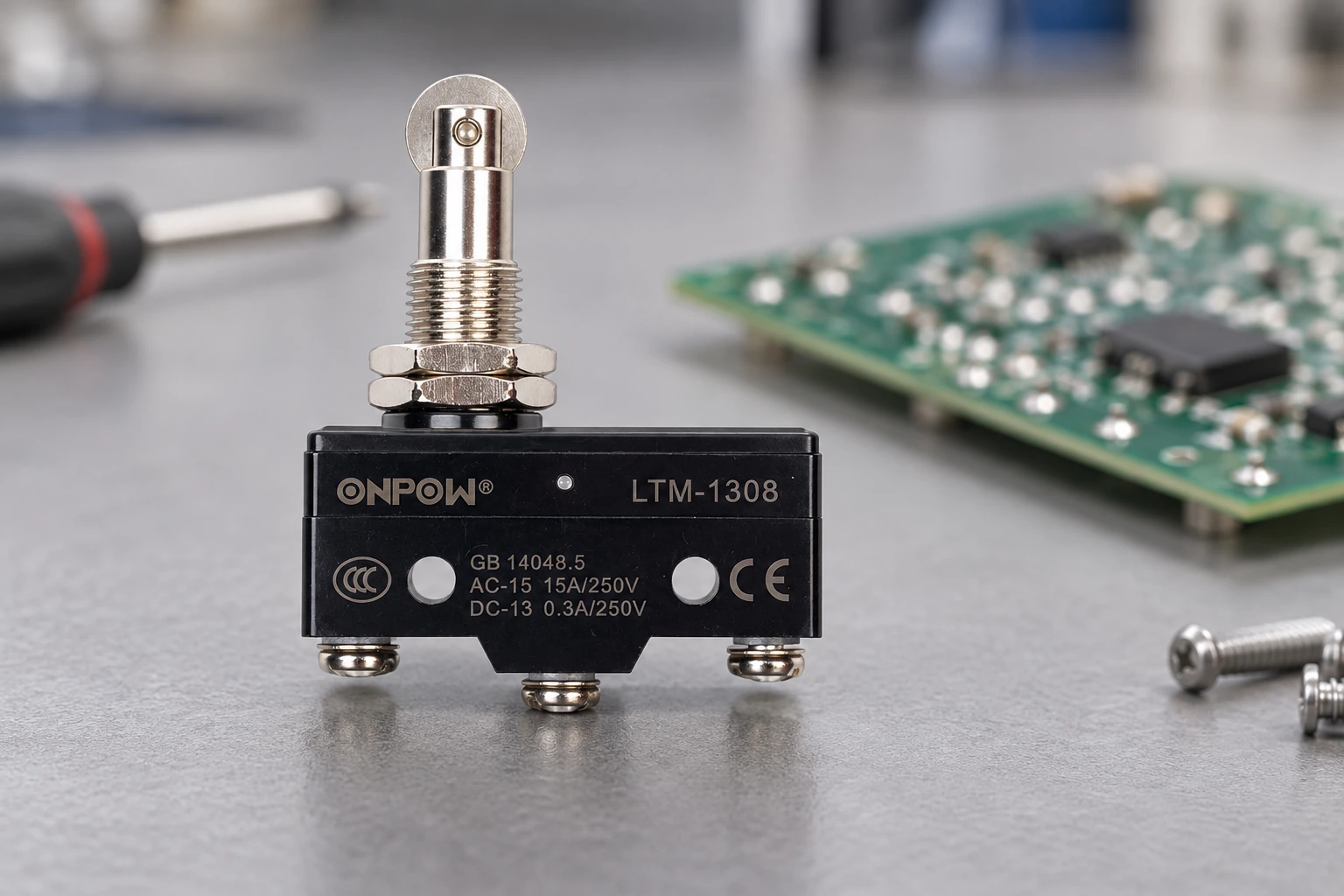
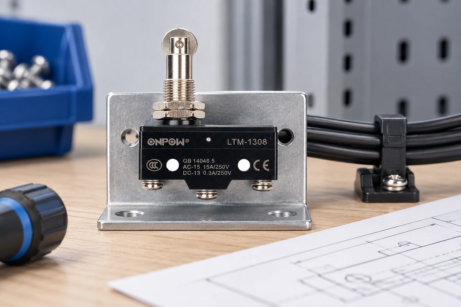
The ONPOW LTM-1308 product page illustrates a real separately mounted mechanical-switch example. The article’s images do not claim that the photographed screw-terminal model is a PCB variant. Request current drawings for available mounting and terminal options rather than extrapolating a PCB footprint from it.
Verify the installation before production release
Use the approved inspection and commissioning process. Installed machines can contain electrical and stored-energy hazards regardless of which mounting method is selected. Qualified personnel should follow the applicable procedures; United States requirements include 29 CFR 1910.147 and 29 CFR 1910.333.
Check the mechanical envelope, support, actuator path, terminations, and isolated contact states. During authorized operational testing, compare the target position with the receiver input and machine response. Inspect the assembly for movement or damage after the planned verification sequence.
Record the approved drawing revision and exact part suffix. For a PCB installation, include the footprint and assembly instructions; for a separate mount, include the bracket and wiring details. Use the industrial micro switch selection checklist to keep these requirements together.
Vídeo educativo
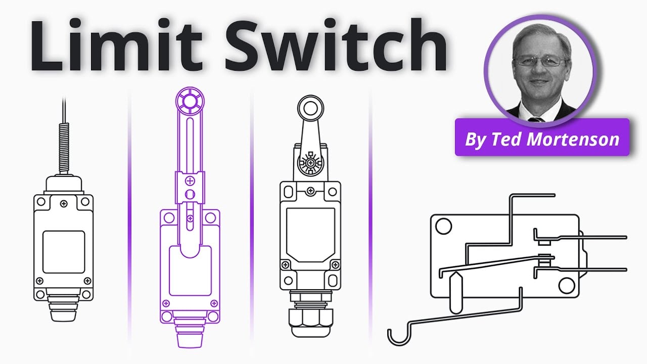
Limit Switch Explained | Working Principles by RealPars. General educational background. Use the selected product drawing and the machine design for the actual circuit and installation. Watch on YouTube.
Perguntas frequentes
Are PCB micro switches electrically different from panel-mounted ones?
Mounting alone does not establish contact function or rating. Compare the exact circuit, declared electrical characteristics, and intended load of each candidate.
Can the solder pins carry all actuation force?
Only the manufacturer’s installation design can establish the permitted support arrangement. Evaluate board flex, mounting features, and repeated mechanical loading.
Can I bend a terminal to fit another PCB footprint?
Do not assume that modification is permitted. Obtain the correct variant or a reviewed adapter design and follow the manufacturer’s terminal-handling instructions.
Is a separately mounted switch easier to replace?
It can be if terminal access and alignment references are designed for service. A cramped or undocumented bracket installation can still be difficult to restore correctly.
What must match in a board-mounted replacement?
Footprint, terminal function, mounting features, actuator geometry, force and travel, assembly process, electrical ratings, and environmental conditions all need confirmation.



