

An LED buzzer combines a visible light signal and an audible signal in one assembly. It can help an operator notice an alarm and identify its source, but the two outputs must be specified separately. Confirm whether the supplied version lights and sounds together, flashes and interrupts the sound, or provides separate control inputs. Then verify that the installed light is visible and the sound is recognizable from the required positions. A product described as an audible-visual alarm is not automatically a safety-rated device, a building alarm, or a suitable replacement for every machine warning.
Why combine sound and light?
Sound can attract attention when a person is not looking at the panel. Light can help identify which machine or station generated the signal. The two channels can therefore support different parts of the operator’s response. The intended meaning must still be defined and trained.
A combined device also simplifies physical placement in some panels. However, sharing one assembly does not make the acoustic and visual coverage identical. A lamp can be hidden behind equipment while sound remains audible; an operator can see a lamp yet fail to hear its buzzer in production noise. Review both paths.
Determine whether the signal identifies an active condition, requests acknowledgement, or communicates another status. These purposes can require different control behavior. A continuous visible indication remaining after sound acknowledgement may be useful in some systems, but it must be part of the approved design rather than an assumption about the component.
Read the exact supplied version
The ONPOW39 buzzer product page lists versions combining continuous light and sound, and versions combining flashing light with interrupted sound. These descriptions identify options to confirm during an inquiry. They should not be extrapolated into independent control inputs, configurable timing, or additional modes that the documentation does not state.
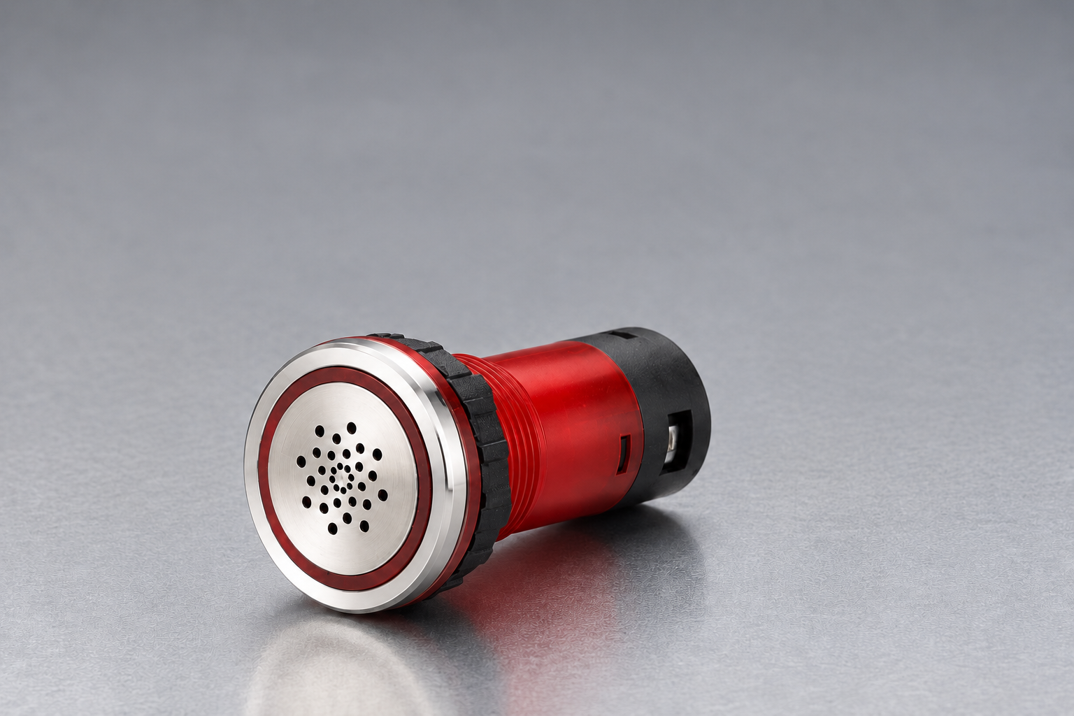
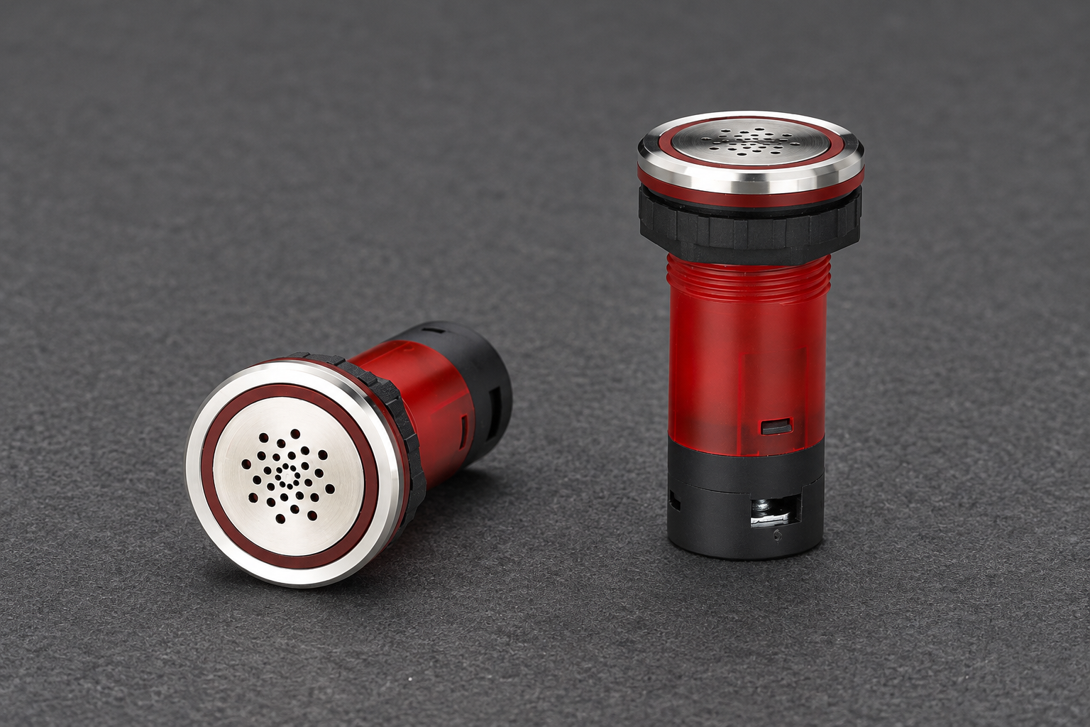
Match the full order code to the offered voltage and output behavior. A photograph can show a perforated face, translucent ring, threaded body and mounting nut, but it cannot establish the circuit inside. Ask for the actual wiring and version documentation before planning the control interface.
Preserve the difference between a reported product parameter and an installed result. A page’s sound value does not guarantee recognition through a cabinet or across a noisy work area. Likewise, a visible colored ring in a product photo does not establish brightness at the intended viewing position.
Coupled outputs versus independent outputs
A coupled assembly can produce its light and sound from one command according to its internal design. If the machine must silence sound while preserving light, that requirement may need a different device arrangement or a documented interface. Do not assume a single-input device provides the necessary independent behavior.
An assembly with separately documented inputs can allow the control system to command the channels independently. In that case, the control program must still define how each output behaves during an alarm, acknowledgement, clearing of the condition, and loss or restoration of supply. Separate terminals are not a complete alarm philosophy.
Ask which behavior is generated inside the device and which must come from the controller. This question applies to flashing, interruption and any tone sequence. It prevents a purchaser from receiving an electrically compatible part that cannot reproduce the required message.
The industrial buzzer wiring guide covers complementary electrical-interface questions. Use it with the exact supplied documentation rather than guessing terminals from the number of wires visible in an illustration.
Define the visual signal’s purpose
Choose the color and timing according to the site’s documented conventions and the machine’s intended meaning. Avoid assigning an arbitrary universal meaning to a color without checking the applicable equipment requirements. Labels, location, mode information and training can be necessary to make the signal unambiguous.
Evaluate normal viewing directions. A panel-mounted luminous ring can work well for an operator facing the panel but provide limited visibility from the side or behind a machine. If broad location visibility is required, review whether a tower light or another signal arrangement is more appropriate.
The tower-light and panel-indicator comparison discusses these placement differences. A combined buzzer can be appropriate for a local station without replacing a higher-mounted indicator used to locate the machine from across a production area.
Consider ambient illumination and obstructions. A bright workshop, reflections on a panel, or a nearby brighter light can affect recognition. Test the actual installation under representative conditions instead of accepting a dark-room photo as proof.
Define the audible signal’s purpose
Record the required tone or sound character, output pattern, listener positions, and response. Sound level is a separate specification from pulse pattern. An interrupted signal is not necessarily louder, and a louder signal is not necessarily easier to identify among other alarms.
Check the exact electrical input under which the sound data apply. Supply variation, an unsuitable controller interface, or an enclosure arrangement can change the practical result. Resolve the electrical configuration before comparing installed acoustic performance.
For U.S. workplaces, 29 CFR 1910.95 addresses occupational-noise requirements. Where the device is part of an employee alarm system, 29 CFR 1910.165 provides relevant alarm-system requirements. Confirm applicability rather than assuming a local machine buzzer automatically fulfills a site-wide alarm role.
The industrial buzzer frequency guide explains the tone-selection question separately. Confirm the offered acoustic character rather than assuming that the visible LED ring determines what the sound will be.
A combined-alarm inquiry checklist
| Requirement | Information to request or define | Acceptance observation |
|---|---|---|
| Alarm meaning | Condition, audience and required response | Operator identifies the intended action and source |
| Light behavior | Color, steady or flashing operation, viewing directions | Indication is recognizable in normal lighting and panel arrangement |
| Sound behavior | Tone, continuous or interrupted pattern, listening positions | Signal is recognizable with representative process noise |
| Input arrangement | Coupled or independent inputs and exact wiring | Controller commands produce the documented outputs |
| Acknowledgement | What stops sound and what remains visible | Acknowledgement does not falsely indicate the fault has cleared |
| Restored supply | Required behavior after interruption | Return of power produces the approved indication sequence |
| Installation | Panel, sealing, connections and environment | Complete assembly matches documented mounting conditions |
The checklist avoids assuming an undocumented feature. The final specification should identify the actual model and its confirmed interface, not merely repeat the phrase “LED buzzer.”
Plan acknowledgement without losing the fault message
Distinguish the alarm command from the condition that caused it. If an operator acknowledges sound, the underlying fault can remain present. Determine how the machine communicates that continuing condition and how the operator knows it has actually cleared.
For a coupled device, sound acknowledgement may necessarily remove the light if both share one input. If that conflicts with the required behavior, solve the component and control-design mismatch before installation. An improvised modification to the device is not a substitute for selecting the correct arrangement.
Consider what happens if an alarm returns after being acknowledged. Define whether the sound starts again, whether the indication changes, and how repeated conditions are handled. Keep these rules in the controlled design so maintenance replacements do not unintentionally change the response.
Mounting and protection apply to the complete assembly
Confirm panel thickness, cutout, fastening arrangement, available rear space, and access to connections from the exact product documents. A correctly sized opening alone does not prove that the assembly is installed properly. The nut, seal, panel surface and wiring space also matter.
Do not equate a water-ingress rating with outdoor suitability or resistance to every cleaning chemical. Temperature, sunlight, corrosion, chemicals and the complete enclosure arrangement are separate considerations. Obtain the relevant confirmation for the actual site.
Preserve the sound opening and visible face according to the instructions. A coating, cover or panel arrangement that blocks the perforated surface can affect the signal. An accessory that protects a component mechanically may also change viewing or listening conditions and needs evaluation.
Verify both channels after installation
Test the device under the approved machine procedure. Observe the commanded state, the actual light behavior, the sound behavior, and their response to acknowledgement and clearing of the condition. Verify at the required operator positions, not only next to the component.
Also check the distinction between a failed signal channel and a correct command. A light that works does not prove the buzzer works, and sound does not prove the visual channel works. Document both results, even when the channels normally operate together.
If the application requires monitoring of failures, confirm how that requirement is achieved in the complete system. Do not assume that a combined housing automatically provides diagnostics or safety integrity. Those claims require actual documentation and system design evidence.
Keep the accepted order code, wiring, control behavior, installation information and test record together. A replacement should reproduce the specified message and interface, rather than merely fit the same panel hole.
The accompanying educational video explains sound waves. It supports the acoustic background of the combined signal; its examples do not establish industrial alarm levels or electrical connection requirements.

Perguntas frequentes
Can I control an LED buzzer’s light and sound separately?
Only if the exact supplied version documents that arrangement. A combined assembly can have coupled outputs. Confirm inputs and acknowledgement behavior before ordering.
Does an LED buzzer replace a tower light?
It can serve a local panel signal, but broader visual coverage depends on placement and viewing directions. Evaluate the required audience and visibility rather than assuming equivalent coverage.
Does a flashing light mean the buzzer also pulses?
Not for every product. Check the exact version’s documented relationship between light, sound and input commands.
Is an audible-visual alarm automatically a safety device?
No. Its role and any required performance must be established by the equipment design and actual documentation. A descriptive product name does not establish safety certification.
What should I test when replacing a combined alarm?
Verify both channels, the command interface, acknowledgement, clearing and restored-power behavior, and recognition from the intended positions under representative conditions.



