

A plug-in relay socket provides the mechanical support and electrical connection between a removable relay and the panel wiring. Choosing it requires more than counting pins: confirm the exact approved relay/socket pairing, terminal mapping, electrical ratings, mounting method, retention accessories, and any internal protection or indication components. A relay that physically enters a socket may still be the wrong electrical or mechanical match. For industrial maintenance, document the relay and socket as a pair so a replacement preserves the intended control circuit. This guide focuses on industrial panel qualification, not automotive harness pin conventions or a universal socket wiring diagram.
Start with a confirmed relay and socket pairing
Obtain the full relay order code and the manufacturer’s approved socket information. A family name can include different contact arrangements, coil versions, terminal styles, or accessories. The approved pair must match the selected configuration, not merely a similar product photograph or another supplier’s description.
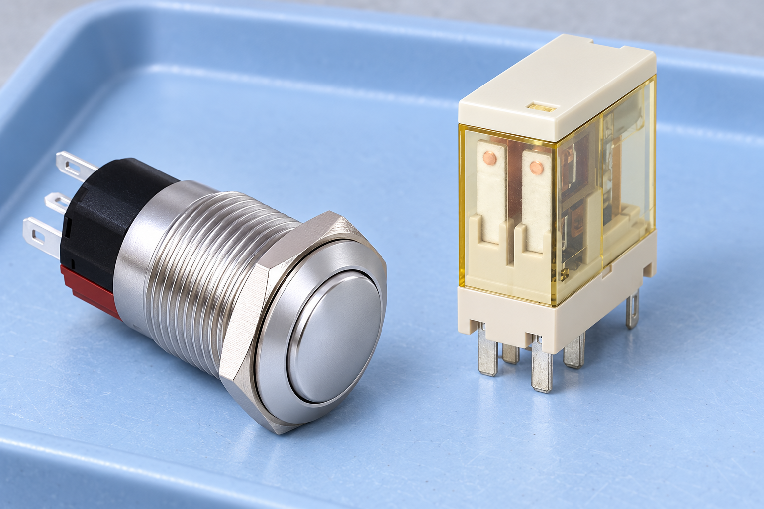
The ONPOW ORJ2SL product page can help identify the relay family to discuss with the supplier. Request the current terminal drawing and confirmed accessories for the exact order code. This article does not identify a specific socket as compatible with ORJ2SL, and the reference-based images intentionally show disconnected real products without an invented socket.
The original Lessons in Electric Circuits relay chapter explains how removable relays can connect through a socket. That educational example establishes the concept, not compatibility for another model. Keep a copy of the approved pairing evidence in the panel documentation before procurement or installation.
Why pin count is an incomplete specification
Pin count does not establish pin spacing, shape, keying, orientation, coil terminal positions, or the assignment of individual contact poles. Two products can have the same number of pins and still use different layouts or functions. The socket’s external terminals may also be numbered or arranged differently from a casual interpretation of the relay’s underside.
Read the actual drawings together. Identify the viewing direction: looking at the bottom of the relay and looking at the wiring side of a socket can create a mirrored interpretation. Confirm the orientation marks and keyed features that prevent an incorrect insertion. Do not redraw a pin map from memory because the part resembles one used on a previous machine.
For circuit interpretation, the electromechanical relay wiring guide separates coil, common, normally open, and normally closed paths. Use that method with the selected diagrams. This socket article addresses how to preserve and document those paths through an approved mounting interface rather than repeating a generic terminal wiring recipe.
Review the whole electrical connection
The usable assembly is limited by the requirements of the relay, socket, conductors, terminals, protection, and installation. A socket current marking does not upgrade the relay’s contact rating, and a relay’s contact rating does not automatically establish the socket terminal’s permitted conductor or installation conditions.
Obtain socket voltage/current information, insulation requirements, conductor sizes and types, terminal preparation, and the specified connection method. Where torque is specified, use the exact manufacturer’s instruction and an appropriate procedure. Do not invent a torque value from another product or assume every screw terminal accepts the same wire construction.
Also review coil and contact paths separately. A socket may carry several circuits at different potentials. The intended clearances, routing, and enclosure must support the complete design. The relay selection guide and contact rating guide help connect the socket review to the wider application without treating mounting hardware as a substitute for load qualification.
Use a pairing checklist before releasing the order
This table is a qualitative procurement checklist. It assigns no universal pin layout, torque, current, or conductor size. Use exact product documents for those values; the Saylor-hosted relay textbook provides background on removable relay construction.
| Check | Evidence required | Reason to hold the order |
|---|---|---|
| Approved pairing | Exact relay order code and listed socket/accessory combination | Only pin count or appearance has been compared |
| Terminal mapping | Both drawings, view direction, orientation and pole identification | Coil/contact assignments are assumed from a different model |
| Electrical limits | Relay and socket ratings for the intended circuits and installation | One component’s headline rating is used for the whole assembly |
| Conductors | Permitted wire construction, size, preparation and connection instructions | A terminal is used outside its documented conditions |
| Montagem | Approved rail or panel arrangement, space and service access | Mounting fits physically but obstructs retention or removal |
| Retention | Approved clip, latch or other restraint where required | An unrelated accessory is chosen because it seems to fit |
| Internal components | Indicator, diode, RC network or other module circuit | Polarity or suppression behavior is unknown |
| Replacement control | Recorded relay/socket codes, diagrams and accepted sample | Maintenance can substitute an electrically different part |
Attach the completed evidence to the purchase request. If the seller cannot confirm a pairing, do not resolve the gap by describing it as standard. An unresolved compatibility question is a reason to obtain documentation or select another documented arrangement.
Retention and access belong to the installation
A plug-in format makes replacement convenient, but convenience alone does not establish that a relay will remain properly seated under its intended conditions. Review the manufacturer’s mounting and retention instructions together with the installation’s vibration, orientation, handling, and access requirements. Use an approved accessory when the selected arrangement requires one.
Provide space for the intended removal and insertion procedure. A crowded cabinet can make maintenance difficult, encourage force on nearby wiring, or prevent inspection of the seating condition. Service access should be checked with the actual layout, not only the footprint of the socket on a drawing.
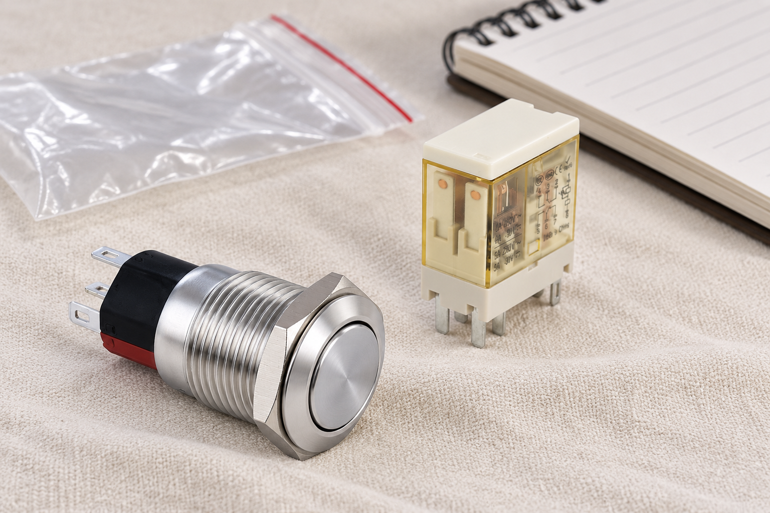
The panel’s manual button also needs its own mounting and wiring review. An ONPOW6116 button shown alongside a loose relay illustrates a control-panel context; it does not show a tested circuit or compatible socket. Keep button contact action, lamp terminals, relay coil requirements, and socket wiring as separate documented questions.
Indicators and suppression can change the circuit
Some sockets or accessories include an indicator or a suppression network. Those features can affect polarity, loading, transient behavior, or relay release. A replacement socket that looks mechanically identical may change the circuit if its internal components differ. Identify the exact accessory code and circuit before accepting it.
A diode associated with a DC coil requires attention to polarity and can affect release behavior. AC coils or other output arrangements require appropriate protection rather than the same generic addition. The DC relay coil suppression guide explains why protection should be reviewed with the driver and timing requirements.
An illuminated socket indicator should not be treated as proof that every relay contact has changed state. It may indicate voltage in one part of the circuit. Record what the indicator actually monitors and what it cannot establish. That prevents maintenance personnel from interpreting a convenient visual aid as a complete functional or isolation check.
Replace a relay through a controlled procedure
Before maintenance, follow the machine’s approved energy-control procedure and the applicable electrical work practices. The official 2025 CFR edition of section 1910.333 is a U.S. workplace reference. Removing a relay is not itself a method of isolating all hazardous energy; the socket wiring and other circuits may remain energized.
Once the equipment is safely prepared for the permitted work, identify the removed relay and socket, inspect for visible damage or abnormal heating, and compare the replacement code with the accepted documentation. Do not force a component into a socket or bend pins to make an uncertain pairing fit. Damage, corrosion, loose terminals, or a changed accessory require investigation under the appropriate procedure.
After the authorized work, verify seating, retention, circuit identity, and the required machine function before return to service. The safe relay testing guide distinguishes limited bench checks from application validation. A relay that clicks on a bench may still be unsuitable for the installed load or control function.
Understand the contact states before checking the mapping
The following educational introduction by Lars Kristjansen explains the difference between normally open and normally closed contacts. That distinction is useful when reviewing a relay/socket drawing pair. The video does not provide the socket pin map for an ONPOW relay, and its demonstration must not replace exact product documentation.

Create a maintenance record that prevents substitutions
Record the panel location, relay order code, socket order code, installed accessory codes, diagram revision, conductor information, and accepted replacement instructions. Include a clear photo of the actual assembly and orientation after the authorized installation is complete. Keep the documentation accessible to the people who order spares, not just the original designer.
When requesting a sample, state what the sample check will establish: product identity, mechanical fit under an approved pairing, access, retention, and the intended functional sequence. Also state what remains outside that check, such as long-term electrical life or performance under environmental extremes. A specific record is more useful than a blanket statement that the socket was tested.
If a supplier changes a part or accessory, review the change before adding it to the spares list. Physical interchangeability does not guarantee that coil polarity, internal suppression, terminal assignments, or permitted installation conditions are unchanged. The aim is to preserve the accepted control circuit during maintenance rather than simply finding a part that plugs in.
Perguntas frequentes
Will any socket with the same pin count work?
No. Pin shape, spacing, orientation, electrical mapping, ratings, accessories, and approved pairing all matter. Count pins as one identification clue, not as compatibility evidence.
Does a socket increase the relay’s current rating?
No. The complete assembly must satisfy the requirements of every component and its installation. A higher socket rating does not change the selected relay’s contact rating for the actual load.
Can a relay be removed while the panel is energized?
Do not treat removal as an isolation procedure. Follow the equipment’s approved maintenance and energy-control instructions and the applicable work practices. Other socket terminals or circuits can remain hazardous.
What should be checked on a socket with a diode?
Confirm the exact internal circuit, coil supply type, polarity, driver compatibility, and effect on release behavior. Do not assume a diode-equipped replacement is equivalent to a plain socket.
Which socket fits ONPOW ORJ2SL?
Request the current approved socket pairing for the exact relay order code from ONPOW. This guide does not establish a compatible socket from a photograph or pin count, and it does not claim a particular socket product is supplied.



