

A 25mm push button switch is the right starting point when the panel drawing calls for a φ25 mounting hole. Select it from that physical interface outward: verify the finished cutout and panel thickness, reserve room behind the panel, then choose operation, contacts, terminals, and any illumination. The face can be wider than 25mm, so measuring the bezel instead of the hole is a common and avoidable error.
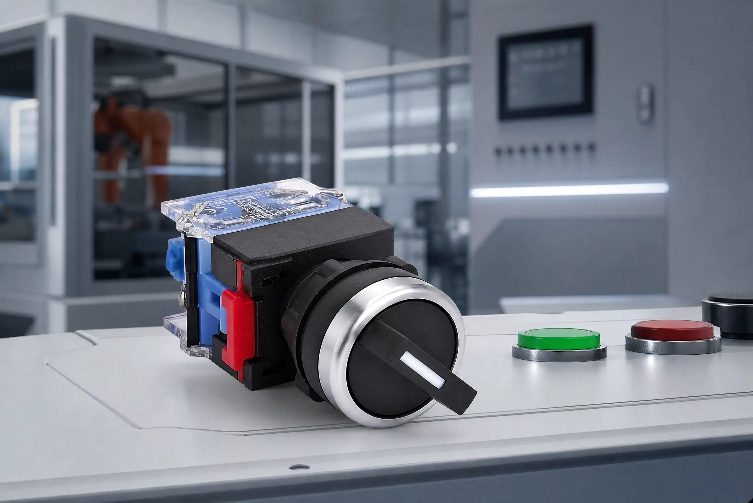
Part 1. Start With the φ25 Panel Interface
“25mm” should mean the installation diameter only when the manufacturer’s drawing says it does. Product listings commonly separate a panel cutout from the visible head, because the threaded body passes through the hole while the bezel remains on the front face. Treat φ25 as a mechanical requirement, not as shorthand for a particular switch function, terminal, or circuit capability.
Start with the panel document. Record the nominal hole size, permissible tolerance, panel material, panel thickness, paint or coating condition, and whether a finished hole already exists. A new panel can be designed around the specified interface; an existing panel must be measured after coating and before a replacement is ordered. A “close enough” hole can leave the retaining hardware unable to clamp correctly or can force an unapproved adapter.
When the drawing specifies a smaller interface, compare the 19mm push button interface before assuming a larger operator will solve a visibility problem. If the drawing says φ22, use the 22mm push button cutout guide as the first comparison point.
Part 2. Decide Whether 25mm Fits Between 22mm and 30mm
Twenty-five millimetres is a distinct mounting interface, not a conversion of 22mm or 30mm. The question is not which diameter sounds more robust; it is which documented body fits the existing or planned opening and leaves a workable rear envelope.
| Panel situation | Best next action | Reason |
|---|---|---|
| New panel calls for φ25 | Specify a φ25 product family and obtain its drawing | The cutout is already the selection anchor |
| Existing φ22 hole | Keep a φ22 operator or obtain a documented conversion approach | A φ25 threaded body does not pass through the smaller opening |
| Existing φ30 hole | Select a φ30 product or a manufacturer-approved reducing solution | A φ25 operator cannot be assumed to clamp a larger opening |
| Face diameter is known, hole is unknown | Measure the opening from the rear or remove the old operator | The bezel diameter does not identify the body |
| Several devices are tightly spaced | Draw front and rear keep-out zones | Nut flats, terminals, and wire exits may conflict even when holes fit |
The visible actuator is still important to the operator, but it is a second decision. It affects marking, reach, illumination, and the spacing of adjacent legends. It does not establish the panel hole. The practical order is therefore cutout, rear envelope, front layout, then electrical configuration.
Avoid using a 25mm choice to blur into a 30mm strategy. A 30mm guide may be useful when a panel actually has a φ30 interface, but the larger interface is a different routing decision. Likewise, a 25mm article should not turn a category current field into a claim about a specific installed load.
Part 3. Check the Rear Envelope Before You Buy
The finished hole tells you whether the body can enter the panel. It does not tell you whether the completed device can be wired, serviced, or removed. Rear clearance must include the threaded or molded body, retaining nut or bracket, terminal projection, connector or lug height, wire-bend radius, and finger or tool access.
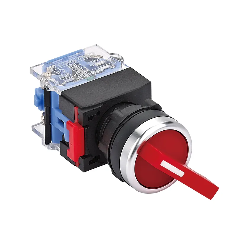
Draw a side view of the enclosure rather than relying on a front-panel CAD circle. Add the manufacturer’s maximum depth from its mechanical drawing, then add the selected terminal and a conservative harness path required by the wiring method. Where a neighboring contact block, terminal rail, PCB, door, or cable duct occupies the same zone, move the device or change the documented configuration before fabrication.
| Элемент обратного конверта | What to request or measure | Why it changes selection |
|---|---|---|
| Body depth | Dimension from panel rear face to deepest body feature | Determines clearance to rails, boards, and doors |
| Retaining method | Nut, bracket, anti-rotation feature, and tool access | A workable hole may still be impossible to tighten |
| Terminal direction | Rear, side, pin, screw, or lead exit | Changes collision and wire-routing risk |
| Harness bend | Wire size, insulation, connector, and minimum bend route | Prevents a tight bend directly at a termination |
| Service path | Space for retightening, testing, and replacement | Keeps a production fit from becoming a maintenance problem |
Online Q&A repeatedly uses the phrase “backside spacing to allow for wiring connections and clearances.” That is the right design question, but it is not a substitute for the product drawing. Do not invent a universal rear-depth number for all 25mm buttons: body length and termination are configuration-dependent.
Part 4. Match the Operation to the Command
Momentary and latching describe what happens after actuation. A мгновенный push button returns when the actuator is released. A защелкивающий push button retains its changed state until the mechanism is actuated again. Choose the behavior from the command logic and the documented product configuration, not from the color or diameter of the button.
A momentary action is normally evaluated for a temporary command or signal. A latching action is evaluated where the intended circuit logic needs a retained state. That high-level distinction is clear, yet the contact sequence, circuit diagram, LED behavior, and available configurations remain product-specific. Ask for the exact circuit function rather than merely writing “start button” in an RFQ.
Contact notation is another separate layer. NO means normally open and NC means normally closed in the stated normal condition; a notation such as 1NO1NC identifies one of each contact state. It does not by itself describe the terminal layout, wire entry, or whether an illuminated variant has a separate lamp circuit. Include the required contact count and state in the request.
For a panel team choosing the visible construction as well as the interface, the metal and plastic operator comparison is useful reading. Material is still not a proxy for operation or contact configuration.
Part 5. Specify Contacts, Terminals, and Front Conditions
Specify the termination only after the physical layout and circuit drawing are available. Screw terminals, pins, solder lugs, leads, and connectors create different rear shapes and harness procedures. The manufacturer’s drawing and exact part configuration are the evidence to use; a category page cannot establish that every member of a diameter family shares one terminal type.
Use this short selection sequence:
- State the normal contact requirement, for example one NO, one NC, or another documented arrangement.
- State whether operation is momentary or latching.
- State the desired terminal form and the wire or connector system it must accept.
- State whether illumination is required and provide lamp voltage, color, and control intent if applicable.
- State the front exposure and the protection target, while identifying which part of the assembly must meet it.
IP and IK should not be merged into a vague “rugged” description. IEC 60529 defines IP classification for enclosure protection, while IEC 62262 defines IK classification for external mechanical impact. A stated value has meaning only for the documented product portion and test condition. The machine enclosure, gasket compression, cable entry, and installation can all matter to the installed result.
Part 6. Route a φ25 Requirement to ONPOW Evidence
For a confirmed φ25 interface, the ONPOW GQ25 Series listing is the appropriate first-party family route. ONPOW’s metal push button category lists GQ25 Series with Panel Cutout Dimension Φ25, Ui 250V, и Ith 5A. Use those exact fields as category-level evidence while asking ONPOW to confirm the selected configuration.
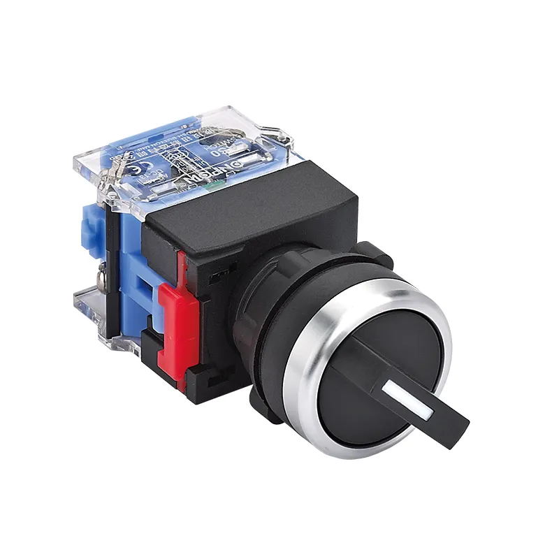
This is a product recommendation for physical-interface discovery, not a claim that every GQ25 configuration has identical terminals, contacts, rear dimensions, or approvals. Ui and Ith are listed fields, not a complete application statement. A buyer who needs a specific load behavior, special function, or terminal arrangement needs model-level documentation and an application review.
The ONPOW category also presents nearby families. Do not select a neighboring GQ25-L or LCA25 item simply because it shares the cutout. Use it only after the manufacturer confirms the requested configuration against the panel, circuit, and ordering details.
Part 7. Set the Fit Boundary and Build the RFQ
Fit Boundary
This guide fits an OEM or panel builder who has a φ25 interface requirement or is free to design a φ25 opening and wants a disciplined selection path. It is not suitable as a substitute for a model drawing, a wiring diagram, an emergency-function assessment, an installed-enclosure evaluation, or a declared operating-duty statement.
Do not use this guide to choose a 25mm unit where the panel is already φ22 or φ30 without an approved mechanical solution. Do not use category values to finalize a model where rear depth, terminal type, contact arrangement, illumination, environmental exposure, or circuit conditions remain unknown.
RFQ checklist
| Ввод запроса предложений | Give ONPOW this information | Selection effect |
|---|---|---|
| Panel interface | Finished φ25 hole, tolerance, thickness, material, coating | Confirms mounting fit |
| Rear layout | Allowed depth, adjacent parts, access side, harness route | Confirms physical clearance |
| Command logic | Momentary or latching; required NO/NC contacts | Narrows the functional configuration |
| Wiring | Terminal preference, wire/conductor details, connector constraints | Checks termination and serviceability |
| Indication | Illumination need, lamp supply, color, marking | Separates lamp requirements from contacts |
| Environment | Front exposure and required documented protection | Keeps protection claims tied to the right product portion |
| Commercial details | Quantity, samples, target date, drawing revision | Makes quotation and confirmation actionable |
Next step: review the ONPOW control-panel selection articles, compare the documented φ25 family route, then send a φ25 panel RFQ with the checklist above. Confirm the exact drawing before punching a new panel or releasing a production purchase order.
Часто задаваемые вопросы
What does 25mm mean on a push button?
It normally identifies the panel mounting cutout or installation diameter when the manufacturer’s drawing says so. Confirm the drawing because a button’s visible face can be larger than its mounting body.
Can I replace a 22mm push button with a 25mm one?
Not directly through the same hole. A φ25 body needs a φ25 interface, so retain the 22mm format or obtain a documented panel modification or approved adapter solution.
How much room is needed behind the panel?
Use the exact product drawing, then allow for the body, retaining hardware, terminal, wire bend, and service access. There is no universal rear-depth number for every 25mm configuration.
Is a momentary or latching button better?
Neither is universally better. Momentary action returns on release; latching action retains a changed state. Choose according to the documented circuit and intended command behavior.
What does 1NO1NC mean?
It denotes one normally open and one normally closed contact in the specified normal condition. Check the product documentation for the exact terminal identification and circuit diagram.
Does a 25mm button have a screw terminal?
It may or may not. Diameter alone does not establish a terminal style, so request the exact configuration and mechanical drawing before committing the harness layout.
Does an IP rating cover the whole machine?
No. IP is a classification for the documented enclosure or protected portion. Confirm what the rating covers and evaluate the completed enclosure, seals, and cable entry separately.
Which ONPOW page should I use for a φ25 requirement?
Begin with the ONPOW metal push button category, which lists GQ25 Series with a Φ25 panel cutout. Ask ONPOW to confirm the exact configuration for your panel and circuit.



