

A 30mm push button switch begins with a φ30 panel interface. Choose it when the finished panel hole is φ30 or when an approved panel redesign creates that interface. Then check the complete rear envelope, operation type, contact logic, terminal form, and exact product documentation. A larger bezel or a higher-looking current field does not convert a 19mm or 22mm opening into a 30mm installation.
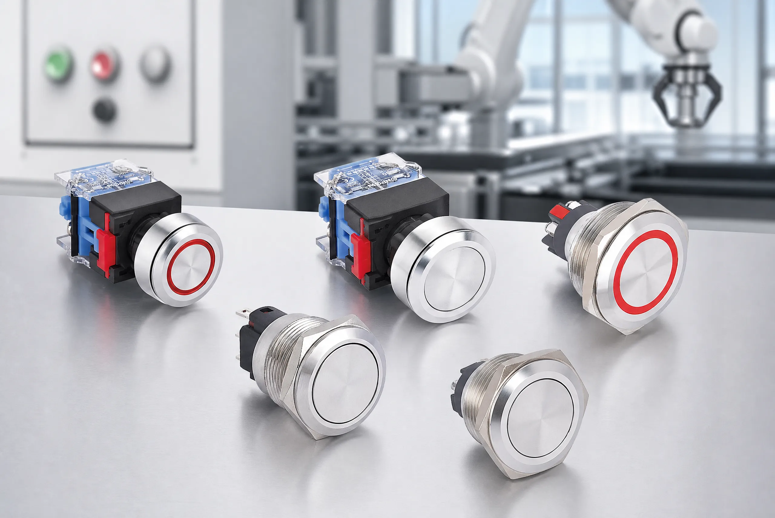
Part 1. Define the φ30 Interface Before Selecting a Product
The “30mm” in a 30mm push button switch normally refers to the mounting interface when the manufacturer lists an installation or cutout diameter of φ30. It does not mean the front actuator is exactly 30mm wide. For example, product catalogues can show a 30mm cutout alongside a larger operator head. Measure the finished hole, not the front bezel.
Start with the panel drawing and record the actual opening, tolerance, thickness, material, coating, and any anti-rotation feature. On an existing enclosure, measure after paint, plating, or powder coating, and inspect from the rear if the old device can be removed safely. On a new enclosure, place the φ30 callout and its keep-out zones in the mechanical layout before selecting terminal hardware.
The mechanical interface should lead the process because it is the least forgiving part to change after the panel is made. A product family can offer different head shapes, illumination, operation, or terminals, yet all of those choices remain secondary if the mounting body cannot pass through the panel or the retaining method cannot be installed.
Part 2. Treat Upsizing From 19mm or 22mm as a Panel Change
Moving from 19mm or 22mm to 30mm is not a drop-in operator substitution. A φ30 mounting body is larger than either opening. Enlarging an existing hole changes the panel design and may affect edge distance, labels, adjacent devices, stiffness, seal geometry, and rear wiring space. Use a documented mechanical change or an approved interface solution; do not rely on a faceplate to conceal a mismatched opening.
| Existing condition | What it tells you | Responsible next step |
|---|---|---|
| New panel requires φ30 | The interface is already specified | Obtain the candidate’s mounting drawing and rear dimensions |
| Existing φ19 hole | The original interface is smaller | Review the 19mm panel-interface guide or engineer a panel change |
| Existing φ22 hole | The original interface is still smaller | Start with the 22mm panel-interface guide before enlarging the panel |
| Existing φ30 hole | The physical interface is compatible in principle | Confirm thickness, retention, rear clearance, and configuration |
| Only the bezel was measured | The cutout remains unknown | Measure the bore and inspect the existing mounting hardware |
The front layout needs its own review after the interface is chosen. Allow room for a legend, fingers or gloves as required by the equipment design, neighboring operators, and a readable indication scheme. Those are usability questions, not proof that 30mm is inherently a better choice than 22mm.
Part 3. Reserve the Rear Envelope
The rear envelope is the space behind the panel required by the body, retaining hardware, terminal, wire exit, wire bend, and service procedure. A panel can accept a φ30 body and still fail the assembly review because a rail, PCB, door, connector, or cable duct occupies the wiring zone.
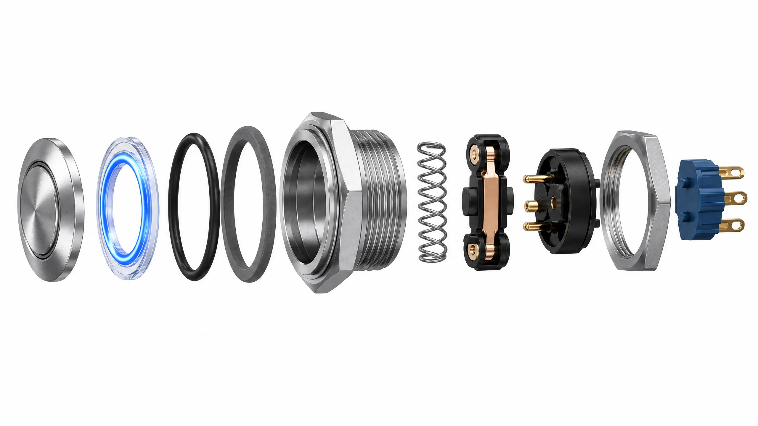
Create a side-section drawing from the panel rear surface. Add the maximum product depth from the selected drawing, not a generic “30mm depth.” Then add the selected terminal shape and the route required by the actual conductor, connector, and bend requirement. Keep a service path for tightening, inspection, and replacement; a product that can be forced into an enclosure is not necessarily maintainable.
| Rear-layout item | What the RFQ or drawing must show | Почему это важно |
|---|---|---|
| Device depth | Panel rear face to deepest body point | Protects clearance to internal hardware |
| Retention | Nut, bracket, locating feature, and tool access | Confirms the device can be secured |
| Terminal exit | Screw, pin, lead, or connector direction | Sets collision and routing zones |
| Harness route | Conductor, connector, bend path, and strain relief | Avoids a sharp bend or blocked terminal |
| Доступ к услуге | Removal and retightening path | Supports production and field maintenance |
Industry Q&A expresses the issue as needing “backside spacing to allow for wiring connections and clearances.” Use that as the inspection prompt. The exact answer always belongs to the product drawing and the panel’s own harness plan.
Part 4. Choose Operation and Contact Logic Separately
Operation describes the actuator behavior. A мгновенный operator returns when released. A защелкивающий operator retains a changed state until it is actuated again. Select one based on the intended command logic and the precise configuration that the product page offers.
Contact notation describes a different layer. 1НО1НЗ means one normally open contact and one normally closed contact in the defined normal condition. It is not a statement about terminal direction, LED wiring, or the circuit function of the complete machine. Verify the exact diagram and terminal markings when preparing the harness.
Write the control requirement in plain language before searching a catalogue:
- What action must occur while the actuator is held?
- What state must exist after it is released?
- How many NO and NC contacts are required?
- Is an indicator needed, and how will it be powered or controlled?
- What exact terminal system will the panel harness use?
This approach prevents a common sourcing error: buying a mechanically correct 30mm operator with the wrong behavior or termination. It also prevents an article about a physical interface from making a load-use conclusion that the exact product documentation has not established.
Part 5. Compare Screw-Terminal and Pin-Terminal Evidence
Terminal type affects both wiring and rear clearance. It must be taken from the exact selected page, not inferred from a 30mm family name. ONPOW’s verified product pages provide a useful example of why this distinction matters.
The GQ30-L-11/S page lists a винтовая клемма. The LCA30-11/S and LCA30-11E/S pages list a switch pin terminal (4.8 × 0.5mm). Those are different documented termination routes, so they should be matched to the approved wiring method and rear keep-out zone. The three pages also list φ30, 1NO1NC, and momentary/latching fields, but the terminal evidence must remain tied to the individual page.
| Вопрос | GQ30-L-11/S page | LCA30-11/S page | LCA30-11E/S page |
|---|---|---|---|
| Монтажный диаметр | φ30 | φ30 | φ30 |
| Структура контактов | 1НО1НЗ | 1НО1НЗ | 1НО1НЗ |
| Режим работы | Мгновенное/Защелка | Мгновенное/Защелка | Мгновенное/Защелка |
| Terminal evidence | Винтовой зажим | Switch pin terminal, 4.8 × 0.5mm | Switch pin terminal, 4.8 × 0.5mm |
| Illumination listing | Not used as an illumination claim here | Non-illuminated page route | Ring illuminated; page lists LED colors and voltages |
For front-condition language, read IP and IK selection guide alongside the exact product page. IP and IK describe distinct protection classifications. They do not eliminate the need to check the protected part, mounting condition, enclosure, seals, and cable entry.
Part 6. Route the Requirement to Exact ONPOW Pages
The product recommendation for a 30mm interface should be evidence-led. Do not make a blanket recommendation for “a 30mm button”; route the request to the page whose documented fields match the configuration question.
Земля GQ30-L-11/S screw-terminal page is the correct route when the RFQ calls for a φ30, 1NO1NC, momentary/latching operator with screw-terminal evidence. Its page lists Ui 250V, Ith 20A, mechanical life ≥1,000,000 cycles, electrical life ≥50,000 cycles, front IP65 with IP67 made to order, and IK09. Record those as exact page fields only.
Земля LCA30-11/S pin-terminal page is the route for the verified non-illuminated LCA30 page with a 4.8 × 0.5mm switch pin terminal. That page publishes a switching-rating table for resistive and inductive conditions; use the exact table only with the stated conditions, not as a universal property of every 30mm product.
Земля LCA30-11E/S ring-illuminated page is the route when the exact page-listed ring illumination, color, and LED-voltage options are needed in addition to the documented φ30 interface and pin termination.

The GQ30-L-11/S page’s Ith 20A is a field to record accurately. It is not a statement that the model will switch a named load directly, that it satisfies a particular motor duty, or that it performs a safety function. These pages are product-selection inputs; the final selection requires the full circuit and product configuration.
Part 7. Apply the Fit Boundary and Send a Complete RFQ
По размеру границы
This guide fits teams with a genuine φ30 requirement, an existing φ30 panel, or an approved redesign that creates a φ30 interface. It is not a reason to enlarge a 19mm or 22mm hole without panel-engineering review. It is also not a substitute for a model drawing, a wiring diagram, an enclosure evaluation, or application-specific circuit verification.
Do not use the GQ30-L-11/S route when the required termination is a 4.8 × 0.5mm pin terminal. Do not use the LCA30 routes when screw termination is a requirement. Do not choose among these pages from a diameter or current field alone.
RFQ checklist
| Input | Include in the inquiry | Why ONPOW needs it |
|---|---|---|
| Panel interface | Finished φ30 hole, tolerance, thickness, material, coating | Confirms mechanical fit |
| Rear layout | Maximum depth, adjacent components, access side, harness path | Checks rear clearance |
| Команда | Momentary/latching and required NO/NC contact state/count | Aligns operating function |
| Termination | Screw or pin requirement, harness/connector details | Selects the documented terminal route |
| Indication | Illumination need, LED supply, color, marking | Routes to a relevant variant |
| Circuit context | Voltage, load details, switching conditions, duty information | Enables application-specific review |
| Окружающая среда | Front exposure and required documented protection | Keeps protection requirements clear |
| Commercial details | Quantity, samples, drawing revision, delivery target | Makes the quotation actionable |
Next step: review related ONPOW panel-control articles, choose the exact product page that matches your terminal and indication requirement, then send ONPOW a φ30 RFQ with the full input set. Obtain drawing and configuration confirmation before releasing the panel or purchase order.
Часто задаваемые вопросы
What hole does a 30mm push button need?
It needs the panel cutout or installation diameter specified by its manufacturer. For the ONPOW pages covered here, the listed installation diameter is φ30mm.
Can I install a 30mm push button in a 22mm or 19mm hole?
Not as a direct substitution. A φ30 mounting body needs a φ30 interface, so changing from a smaller hole requires a documented panel modification or approved interface solution.
Is 30mm the button face diameter?
Not necessarily. The bezel can be wider than the mounting opening. Confirm the installation diameter and all front dimensions on the product drawing.
How much rear depth should I allow for a 30mm switch?
Use the exact product drawing and add space for retaining hardware, terminals, wire bend, and service access. There is no reliable generic depth for every 30mm configuration.
What does 1NO1NC mean?
It means one normally open and one normally closed contact in the defined normal condition. It does not replace the model’s wiring diagram or terminal identification.
Does GQ30-L-11/S have screw terminals?
Yes. The verified ONPOW GQ30-L-11/S page lists “Screw Terminal.” Confirm the selected configuration and rear wiring space before ordering.
Are the LCA30 pages screw-terminal versions?
No. The verified LCA30-11/S and LCA30-11E/S pages list a switch pin terminal sized 4.8 × 0.5mm.
Can Ith 20A be read as a direct-load rating?
No. GQ30-L-11/S lists Ith 20A, but that field alone does not state a validated load type, utilization category, motor duty, switching frequency, or direct-load recommendation.



