

Key removal positions specify where the key can be withdrawn from an industrial key switch. They are independent of the number of switch positions, the contact arrangement and whether the operator is maintained or spring return. To order correctly, name every mechanical position, state whether withdrawal is permitted there and record the electrical state that remains after removal. Then compare that behavior with the machine’s access and operating procedure. A switch supplied with two keys does not necessarily allow withdrawal in two positions, and removing the key from an ordinary control switch does not establish hazardous-energy isolation.
Start with the behavior after the operator leaves
The useful design question is what should remain possible after an authorized person selects a position and walks away. Should the selected mode remain active? Should the key stay captive while that mode is selected? Should the operator return to a neutral position before the key can be removed? These are distinct requirements.
Consider a maintained mode selector. Permitting key removal in the selected mode can allow the operator to leave the setting in place while retaining the key. That may support an intended access procedure, but it can also leave other workers uncertain about who can change the state. The operating procedure and visible mode information need to address that result.
For a temporary command, withdrawal may be restricted to the rest position. However, do not infer that restriction from the presence of a return spring. Request the exact removal-position specification for the supplied lock and operator.
Number of positions does not define withdrawal permission
A two-position key switch can have different withdrawal arrangements depending on its design and options. A three-position operator can also offer different permitted positions. The position count identifies mechanical selections; it does not establish where the lock releases the key.
Likewise, the number of keys in the package says nothing about the removal pattern. Two keys usually describe the supplied quantity, not two electrical functions or two withdrawal positions. Avoid including that package detail as the main specification.
Use a position diagram and a written table. Define names such as “rest,” “setup” and “automatic” rather than relying only on left and right. Then include the drawing’s rotation convention so that the panel builder and supplier refer to the same viewpoint.
The ONPOW key and selector switch category is the product starting point. Its head styles and series names help identify a device family, but the exact removal pattern requires confirmation for the ordered configuration.
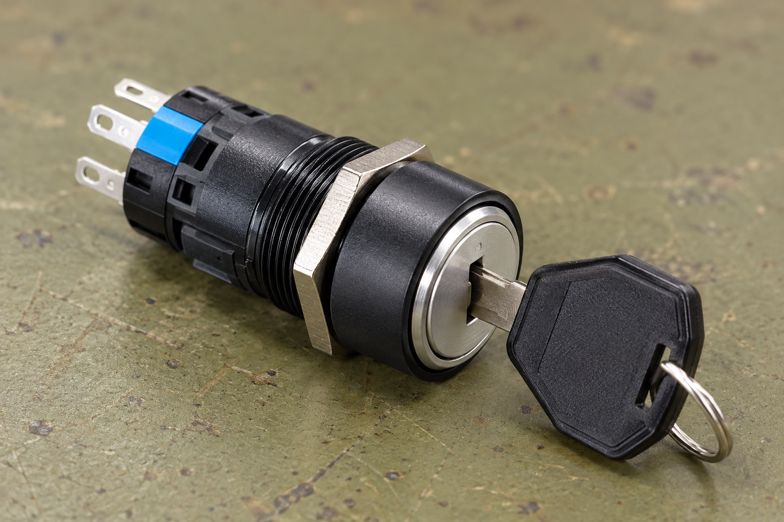
A removal-position specification table
A completed table should describe the intended machine behavior without guessing at a supplier’s lock option. The example below lists the information needed for each position rather than prescribing a universal arrangement.
| Field for every position | What to record | What it prevents |
|---|---|---|
| Position identity | Named state and matching rotation diagram | Ambiguous references to left, right or position two |
| Mechanical action | Maintained or return direction | Assuming withdrawal and spring return are the same feature |
| Key removal permission | Permitted or captive, confirmed for the exact version | Ordering from position count alone |
| Contact state | State of each labeled contact at that position | Leaving an unspecified electrical state after removal |
| Controller interpretation | Requested mode, accepted mode or temporary command | Confusing the key’s mechanical state with actual machine operation |
| Indication after removal | How other workers identify the current state | A selected mode becoming invisible when the keyholder leaves |
| Responsible keyholder | Access procedure and spare-key policy | Treating any available spare as equivalent authorization |
Attach the completed table to the quotation request, drawing approval and acceptance record. The supplier can then confirm whether the required pattern is available instead of interpreting an incomplete phrase such as “key removable switch.”
Contact states must survive the handover clearly
If a maintained operator remains selected after removal, document which contacts remain open or closed. Removing the key need not change the contact state. If a spring-return mechanism returns before withdrawal, record both the held state and the resulting rest state.
A contact table should identify actual terminal markings. Do not assume that a normally open contact is open in every position in which the key is absent. “Normally open” refers to the defined reference state and must be interpreted through the exact device documentation.
The two-position key switch guide provides context for maintained selection. The momentary key switch guide explains temporary actions. This article adds the separate withdrawal requirement, rather than replacing either contact-action topic.
When a controller accepts or rejects a mode request, keep that distinction visible. A removed key can coexist with a rejected request or a stopped machine. The panel should communicate the state that matters to the task, not just the last physical movement of the operator.
Captive keys and normal access control
Keeping a key captive in a selected position can be useful in a documented operating procedure. It can make withdrawal conditional on returning the operator to another position. However, ordinary key-switch capture should not be described as a complete safety interlock without the appropriate device and system assessment.
Define who is authorized to operate the switch and who manages spare keys. If multiple matching keys are freely available, possessing a key may provide little practical access restriction. That is an organizational question as well as a product choice.
The HSE introduction to human factors highlights the relationship among the job, the individual and the organization. For key management, the useful implication is to review the operating task and key-control procedure alongside the hardware. A mechanical option alone cannot establish that the intended access policy is followed.
Avoid claiming that a particular key type is secure against unauthorized copying or misuse unless the exact lock system and evidence support that claim. Ordinary industrial keyed operators are commonly selected for controlled operation, and that purpose should be described accurately.
Ordinary key switches and trapped-key systems
A control key switch and a purpose-designed trapped-key interlocking system are different product and system concepts. Do not assume that a captive-key option on a normal operator provides the same sequence control, isolation or safety properties as an assessed interlocking arrangement.
If the machine requires a safety-related access sequence, send that requirement to the responsible designer. The selection must consider the complete system and applicable requirements. A general article cannot turn a photographed operator into a verified safety device.
The US hazardous-energy rule, 29 CFR 1910.147, provides context for separating normal control from energy isolation. Removing the operating key does not necessarily isolate every energy source. Use the employer’s documented energy-control procedure and the rules applicable to the installation.

Make the selected state visible to other workers
If a key is withdrawn while a mode remains selected, the keyholder is not the only person who needs to understand the state. Labels, position markings and any indicator should remain meaningful for the next operator or maintenance worker.
Where illumination is used, define whether it communicates a selection, controller acceptance or supply availability. The illuminated key switch guide develops that display question. A lamp cannot establish withdrawal permissions, and a removed key cannot establish what the lamp means.
Review the actual viewing position and task. A small mark visible only from directly in front of the switch may be inadequate for a worker approaching from the side. Do not solve every ambiguity with an additional color; improve the message and panel arrangement where necessary.
Replacement parts can change the access procedure
Two operators can share a head size and contact arrangement while allowing key removal in different positions. An apparently convenient replacement can therefore change how a machine is left selected or who can change its mode.
Compare removal permissions explicitly when replacing a device. Also compare rotation action, contact states, lock/key compatibility and the panel’s labels. A replacement that accepts an existing key may still have a different removal pattern; a replacement with a new key can change the access-management process.
Do not file, modify or defeat the lock mechanism to obtain a desired withdrawal position. Ask the supplier for the appropriate documented version and preserve the equipment’s approved design. If the original specification is unknown, keep that uncertainty visible until the responsible person confirms the intended behavior.
Acceptance and records
Before installation, compare the delivered part identification with the approved diagram and withdrawal table. Under the appropriate isolated inspection procedure, verify each position’s mechanical behavior, key removal permission and contact state. Do not infer acceptance from one successful key turn.
Commission the controller response and indication through the approved equipment procedure. Check what remains selected after withdrawal and what happens after power interruption when relevant. Record discrepancies rather than changing the procedure informally to accommodate an unsuitable part.
Keep the exact option code, approved table and key-management instructions with the machine records. For a quotation from ONPOW, include a marked position diagram and specify which positions must release or retain the key. Ask for written confirmation before treating the quotation as the final access specification.
Further learning: a contact is an input to a sequence
The RealPars lesson explains the relationship between wiring diagrams and PLC programs. It supports the distinction between a physical key position and the controller’s response. It does not demonstrate a particular lock’s withdrawal behavior or validate a trapped-key safety system.

Frequently asked questions
Does a two-position key switch release the key in both positions?
Not necessarily. Position count and removal permissions are separate specifications. Request the exact withdrawal table for the supplied lock and operator version.
Does spring return mean the key can be removed only at rest?
Do not assume so. Return action describes mechanical movement after release; key removal describes the lock’s withdrawal permissions. Confirm both independently.
Does removing the key open the contacts?
That depends on the defined operator action and contact table. A maintained position can remain selected after removal. Record the resulting state for every permitted withdrawal position.
Is a captive-key operator a complete safety interlock?
An ordinary captive-key option does not establish a complete safety system. Safety-related access sequences require suitable equipment, documented design and the applicable assessment.
What should be checked during replacement?
Compare removal positions, operator action, contact table, key compatibility and panel indication. Matching the cutout or accepting a familiar key is not enough to establish an equivalent configuration.



