

An emergency stop button symbol can refer to three different things: the electrical contact on a circuit drawing, the graphical identification of an emergency stop function, or the physical marking on a red mushroom operator. Those meanings should be kept separate when reading or preparing documentation. A contact symbol explains a circuit state; it does not prove that the operator latches, that the circuit is monitored or that a machine meets its safety requirements. This guide helps purchasing and maintenance teams reconcile a drawing legend with a real button, its contact assembly and the machine’s functional description.
Start by identifying the document you are reading
A wiring schematic, panel layout and operating instruction serve different purposes. On a schematic, the reader needs to trace connections and determine contact states. On a panel layout, the reader needs to locate the device. In an operating instruction, the reader needs to understand when and how to use it. Reusing the same icon without explaining the document context can make those purposes harder to distinguish.
Check the drawing legend before interpreting a symbol. It should identify the convention or symbol library used and explain any project-specific notation. Do not assume that a drawing downloaded from another country, a CAD library or a maintenance forum uses the same reference conditions and designations as your machine. If the legend is missing, request it rather than assigning a meaning from the icon alone.
The practical consequence is simple: write down what a mark is intended to communicate. “This is the operator location,” “this is one NC contact” and “this identifies the emergency stop function” are different statements. Once those statements are clear, the drawing can show the relationship between them without asking the reader to infer the whole system from a single red circle.
Separate the operator from its electrical contacts
The visible mushroom head is the operator. One or more contact elements behind it produce electrical state changes. A drawing may show the operator in one location and its contacts elsewhere on the same sheet or on another sheet. Device references and cross-references are what connect those representations. Proximity on the page is not a reliable substitute for an explicit association.
An NC contact symbol describes a state under the reference conditions stated for the drawing. It does not by itself specify the physical head, release method or contact opening characteristics. Likewise, a red mushroom photograph does not reveal how many NC contacts are supplied. Read the operator description and the contact arrangement together, using documentation for the exact ordering code.
Mechanical linkage should be clear where multiple contact symbols belong to the same actuator. If a schematic includes both an auxiliary reporting contact and contacts assigned to a safety input arrangement, label their roles. Otherwise an installer might treat an available auxiliary contact as interchangeable with one that has a different specified function. Clear documentation prevents that ambiguity before wiring begins.

State the reference condition explicitly
“Normal” is easy to misunderstand on a drawing for equipment that is currently stopped. A machine can be stopped with an emergency operator released, stopped with it latched, or isolated for maintenance. Those conditions are not equivalent. The schematic notes should identify the reference state of the operator and the relevant supply conditions rather than relying on the everyday meaning of normal.
A useful review question is: what would each depicted contact be doing with the operator released under the drawing’s stated conditions? Then ask what changes when the operator is actuated and what remains changed until the defined release action. Answering those questions is more informative than memorizing an icon. Use the component drawing to resolve the actual contact behavior.
Do not replace a manufacturer’s terminal drawing with a generic legend. The legend explains the symbol language; the terminal drawing identifies the supplied hardware. Both are needed when reconciling a schematic with a replacement device. If a diagram shows two contacts but the ordered assembly provides only one of the required type, correcting the graphic alone does not solve the component mismatch.
Distinguish button marking from a circuit symbol
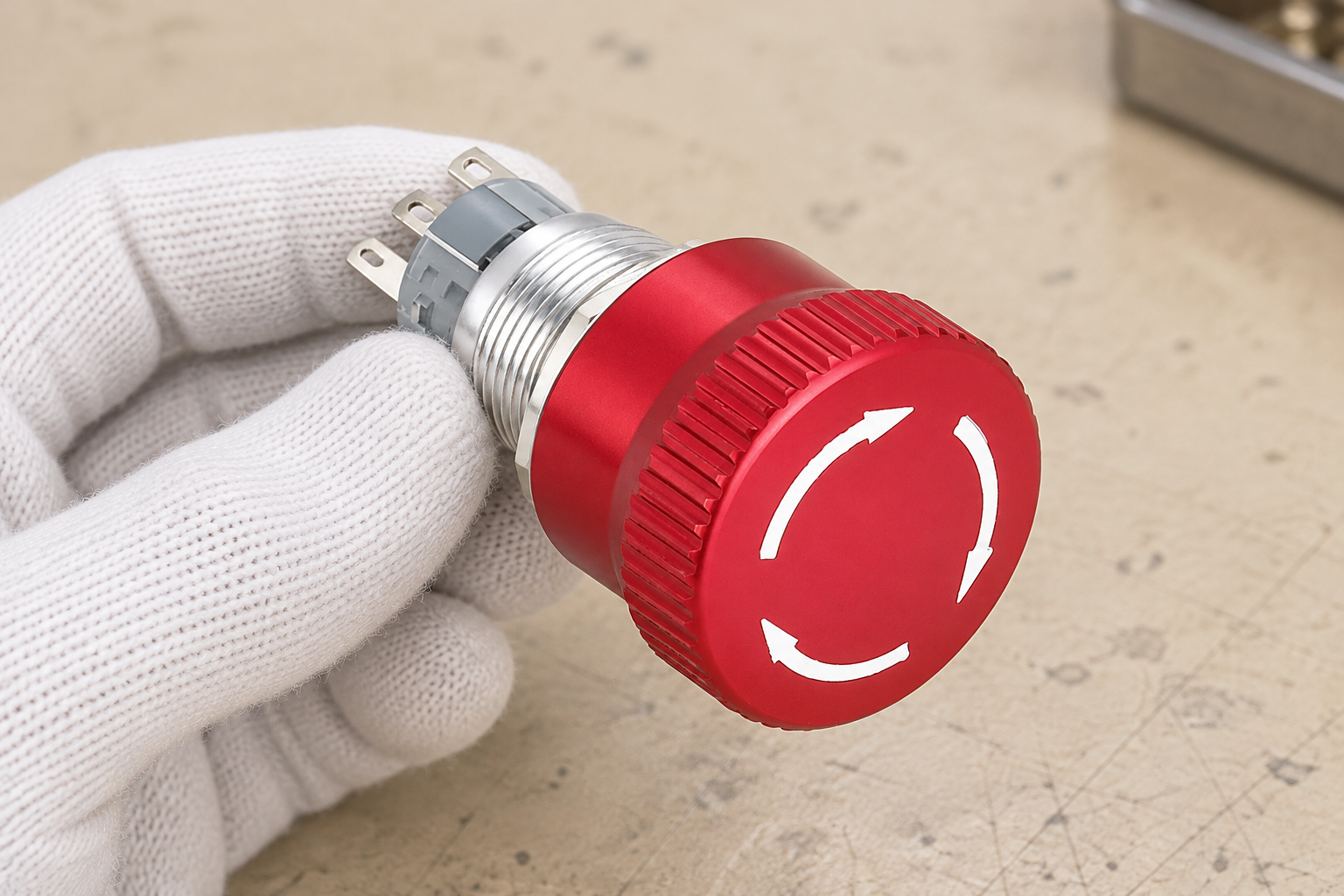
Arrows on the face of a mushroom operator can communicate a release action. They are physical markings, not a drawing of the internal contact circuit. A mounting-ring label can identify an emergency function or a machine zone, but that label also cannot establish the internal contact arrangement. Photograph those markings during an equipment survey and record their purpose separately from the electrical details.
Avoid inventing an emergency symbol by combining familiar icons. A power symbol, ordinary stop label and emergency identification are not automatically interchangeable. The appropriate graphical identification, colors, text and location should follow the applicable standards and the machine documentation. Check the selected symbol in its authoritative register instead of tracing an image from a stock artwork site.
The IEC database of graphical symbols for use on equipment is a reference entry point for equipment markings. The HSE guidance on safe use of work equipment provides UK work-equipment context, while the applicable standards must be checked for the actual machine. These are different reference functions: neither a symbol database entry nor a standard title approves a particular machine design.
Give every physical device a traceable identity
Use a consistent device reference to connect the panel location, schematic contacts, bill of materials and maintenance record. The naming system can differ between projects, but the association must remain unambiguous. If two red buttons control different stop zones, their records should make that distinction clear. A generic “E-stop” description in the parts list leaves too much room for a wrong replacement.
Include the exact operator code, contact block or assembly code and the required mounting information. Where options are available, record the supplied option rather than just a family name. An engineering change that alters contact configuration should update the bill of materials and schematic revision together. Otherwise a technically correct drawing may describe a device that procurement no longer supplies.
The ONPOW LAS1-AGQ-TS product page illustrates why component confirmation matters. Its published descriptions include a mushroom-style appearance and a stated contact action; those facts should not be transformed into a claim about a validated safety function. Ask for the exact operator action, contact diagram and documentation required for the intended machine. The reference images here explain appearance only.
Use a symbol-to-hardware review table
This qualitative table describes what each representation can establish and what must be checked elsewhere. It is an aid to document review, not a substitute for a controlled symbol standard or component instruction. Apply it to the actual drawing revision being considered.
| Representation | What it communicates | What it does not establish by itself | Record to check |
|---|---|---|---|
| NC contact symbol | Reference-state contact relationship | Operator action, terminal layout or safety performance | Exact contact drawing |
| Operator graphic | Type or location of a physical control | Number and characteristics of contacts | Operator specification |
| Mechanical association | Contacts linked to one device | Controller fault detection | Device record and controller instructions |
| Release arrows on head | Intended physical manipulation | Restart permission or isolation | Operating instructions |
| Emergency identification label | Function or location identification | Correct wiring or validated stop behavior | Applicable marking requirements |
| Device cross-reference | Association across drawing locations | Installed component conformity | Bill of materials and inspection record |
Read safety behavior beyond the symbol
An emergency stop function is a system behavior, not a decorative mark. The drawing and functional description need to explain the defined stop zone, the response of the controlled equipment and the reset and restart conditions. The HSE machinery safety introduction provides context for emergency controls within broader machine risk reduction. The physical button is one component in that wider approach.
Do not interpret a reset arrow as permission for automatic restart. Releasing the operator, resetting a controller and issuing a normal start command are separate actions to examine. If the drawing does not explain their relationship, raise a documentation question. Adding an extra icon beside a start button does not resolve an undefined sequence.
Also separate emergency stopping from maintenance isolation. A stopped machine may retain electrical, pneumatic or mechanical energy. Symbols that identify operating controls do not describe every energy source or the procedure for making work safe. The isolation instructions and machine risk assessment need their own review, especially when a maintenance task involves reaching behind a panel or replacing contact elements.
Resolve inconsistencies before replacing hardware
When the drawing and installed hardware disagree, document the discrepancy with the device reference, drawing revision and component identification. Do not alter the contact designation to match a quick continuity reading without understanding the operator state and test conditions. An unexplained mismatch may reflect a wrong replacement, an obsolete drawing or a fault that requires investigation by competent personnel.
For procurement, distinguish appearance compatibility from functional compatibility. Two devices can share a red mushroom head and mounting size while differing in contact configuration or operating action. A supplier should receive the functional requirements and document request, not just a photograph. The replacement approval should identify which characteristics were verified and which remain unresolved.
For supporting concepts, read selector switch symbols and contact tables and limit switch symbol examples. Those articles address related drawing conventions without replacing the emergency stop functional review. Use emergency stop troubleshooting for a separate guide to organizing reset and fault observations.
Use educational examples carefully
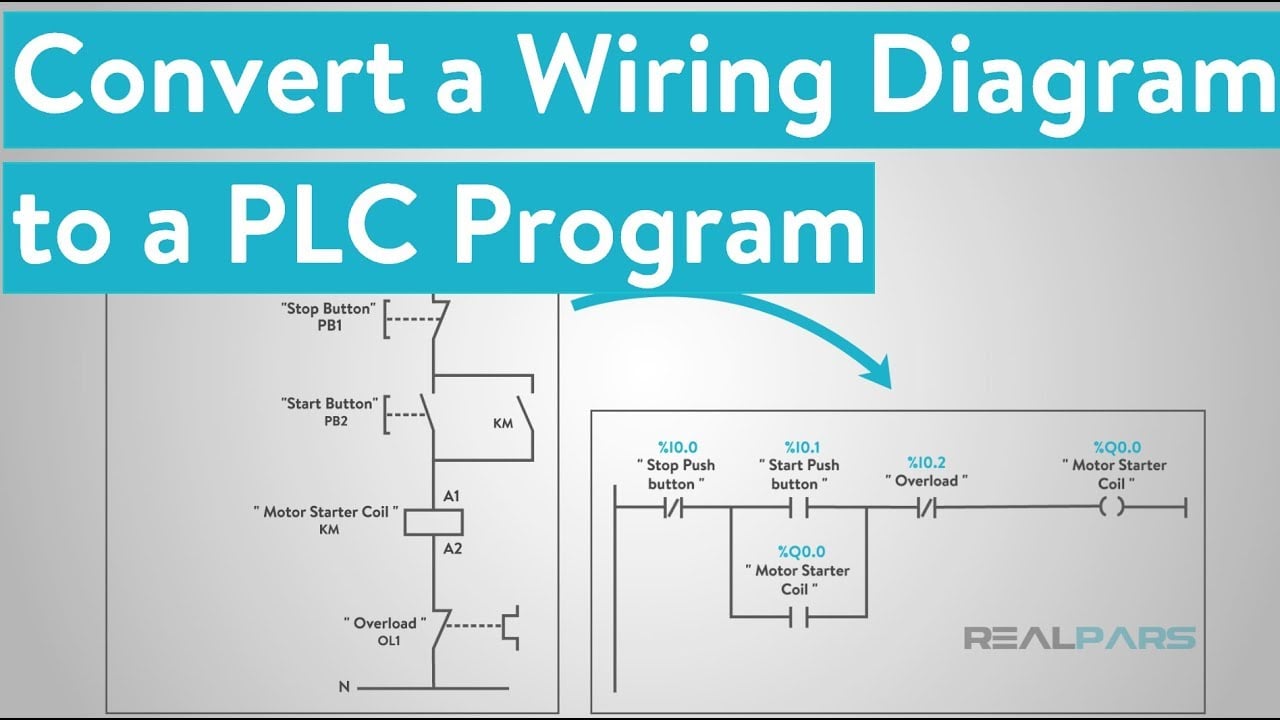
The video below explains the relationship between a basic wiring diagram and PLC logic. It can help readers separate a contact drawing from a control decision. It is background education, not an approved emergency stop circuit, symbol standard or safety controller instruction. Any example must be reconciled with the exact machine documentation before it informs an installation decision.
Before requesting a quote, prepare the device reference, panel location, operator appearance, required action, contact arrangement and applicable document list. Attach the current schematic excerpt and clearly identify unresolved requirements. Contact ONPOW for component clarification; have the responsible machine designer review the complete stop function and replacement decision.
Frequently asked questions
Is an NC contact symbol an emergency stop symbol?
It describes a contact state under defined conditions. Device references and the functional description establish whether that contact belongs to an emergency stop function.
Do the arrows on a mushroom button describe its wiring?
No. They indicate a physical operating or release action. Use the exact component contact diagram to establish the electrical arrangement.
Can a power icon be used as emergency identification?
Do not assume the icons are interchangeable. Verify the required identification against the applicable symbol references, standards and machine documentation.
Why do two contact symbols share one device reference?
They may represent separate contacts associated with the same physical operator. Check the linkage and cross-references to confirm the intended arrangement.
What should I do when the installed button differs from the drawing?
Record the component and drawing revision, document the mismatch and obtain competent review before replacement or wiring changes. Do not resolve an unknown function by changing labels alone.



