

For a push button connected to a PLC input, sinking and sourcing describe the direction of conventional current through the input circuit. A mechanical dry contact does not create either behavior by itself: it completes the current path established by the power supply, input electronics and common terminal. Identify the exact input module and its wiring diagram before choosing which supply conductor the contact switches. Treat the LED as a separate circuit unless the selected device documentation explicitly shows an internal connection. This guide covers ordinary control inputs, not the design or approval of a machine safety function.
Begin with the input module, not the button color
Record the controller model, input-module order code, revision and channel group. A terminal marked COM can be shared by several channels, and its permitted connection depends on the module. Do not assume that the adjacent output group uses the same arrangement. A drawing copied from another cabinet may look familiar while describing different electronics.
The practical question is simple: where does current start, which input element does it pass through, and how does it return to the supply? Trace that complete loop on the manufacturer’s circuit before assigning terminals. If the manual provides selectable input modes, record the configuration as well as the external wiring. Hardware selection and software configuration must describe the same installation.
For current-direction terminology, NI’s industrial digital I/O explanation distinguishes a sourcing device that supplies current from a sinking device that provides the return path. The article concerns digital outputs; use it for vocabulary, then use your input module’s own manual for its actual terminals and limits.
Understand the two ordinary DC current paths
With a conventional sinking input, the input electronics provide a path toward the negative supply reference. An external contact can complete the positive-side feed to that input. With a conventional sourcing input, the input electronics provide current and the external contact completes the path toward the negative reference. These descriptions are conceptual, not a universal terminal diagram.
A passive isolated contact can be suitable in either arrangement if all its applicable electrical characteristics are satisfied. It has no PNP or NPN transistor merely because it sits in a circuit commonly described with those terms. An electronic touch switch, illuminated assembly with shared connections, or powered sensor must be evaluated differently because it may not present an isolated contact at all.
Do not decide from wire colors alone. Trace the supply rails and input common on the released drawing, check the manufacturer’s terminology, and mark the intended current direction. Different documentation sometimes describes the field device and the receiving input from different viewpoints, which makes a label without a circuit especially easy to misunderstand.
Use a compatibility record before connecting conductors
The following table is a review tool for ordinary DC inputs. It contains no universal current, voltage or timing limits; obtain those from the selected module and button documentation.
| İnceleme kalemi | Input-module evidence | Push-button evidence | Release question |
|---|---|---|---|
| Current path | Internal input diagram and common connection | Isolated contact diagram | Is there one documented supply-to-return loop? |
| Signal levels | Guaranteed on/off ranges and input current | Applicable switching duty and minimum-load information | Are both states reliably distinguishable? |
| Temas hareketi | Required software state at rest | NO/NC and momentary/maintained action | Does pressing and releasing produce the intended command? |
| Aydınlatma | Available lamp supply or output circuit | Separate lamp terminals and exact lamp rating | Is the lamp independent of the input signal? |
| Zamanlama | Input filter and program treatment | Contact behavior and operating use | Can a normal press be detected without duplicate commands? |
| Gruplama | Shared commons and isolation boundaries | Number of independent contacts | Are channel groups kept within their permitted arrangement? |
Keep the table with the panel drawing rather than in an informal purchasing message. A reviewer should be able to find the source for every decision without reconstructing the installation from a photograph. An unresolved field is a reason to obtain the missing documentation before release.
Check signal duty as well as the maximum rating
cURL Too many subrequests by single Worker invocation. To configure this limit, refer to https://developers.cloudflare.com/workers/wrangler/configuration/#limits cURL Too many subrequests by single Worker invocation. To configure this limit, refer to https://developers.cloudflare.com/workers/wrangler/configuration/#limits cURL Too many subrequests by single Worker invocation. To configure this limit, refer to https://developers.cloudflare.com/workers/wrangler/configuration/#limits.
cURL Too many subrequests by single Worker invocation. To configure this limit, refer to https://developers.cloudflare.com/workers/wrangler/configuration/#limits.
cURL Too many subrequests by single Worker invocation. To configure this limit, refer to https://developers.cloudflare.com/workers/wrangler/configuration/#limits.
Keep the LED from creating a misleading signal path
cURL Too many subrequests by single Worker invocation. To configure this limit, refer to https://developers.cloudflare.com/workers/wrangler/configuration/#limits.
cURL Too many subrequests by single Worker invocation. To configure this limit, refer to https://developers.cloudflare.com/workers/wrangler/configuration/#limits cURL Too many subrequests by single Worker invocation. To configure this limit, refer to https://developers.cloudflare.com/workers/wrangler/configuration/#limits cURL Too many subrequests by single Worker invocation. To configure this limit, refer to https://developers.cloudflare.com/workers/wrangler/configuration/#limits.
Specify what illumination means: available control power, command received, permitted operation, or confirmed equipment state. Each requires a different control decision. The visual label and operator instructions should match that meaning so a technician does not mistake an indication for verified process feedback.
Verify the input without using an unsafe shortcut
Electrical inspection and testing require competent personnel and an appropriate isolation procedure. HSE’s electrical safety questions provide general context for safe work; the machine’s procedure determines how the specific inspection is performed. Do not bridge unknown terminals or defeat an interlock to discover which common arrangement works.
Start with the de-energized wiring and identification checks. Confirm the contact terminals, the input channel, its common group and the intended supply reference. An isolated contact check can establish which pair opens or closes, but it does not establish compatibility with powered input electronics. Remove test equipment and restore the documented circuit before controlled functional testing.
During authorized commissioning, compare three observations: contact operation, the module’s input indication, and the controller’s monitored input state. Record press and release separately. If the physical input changes but the expected program behavior does not, investigate mapping and logic rather than repeatedly replacing the button. If neither indication changes, investigate the circuit path and its permitted signal conditions.
Include release, power restoration and realistic press timing
A momentary button supplies a temporary condition; software decides how that condition becomes a command. Test a short normal press, a sustained press and release. Record whether the application uses a level or an edge and whether an input filter can suppress the shortest intended operation. Keep debounce handling separate from current-direction selection.
Also test the approved behavior after loss and restoration of control power. A maintained contact may already be closed when the controller restarts. Whether that condition should be ignored, acknowledged or processed is a system requirement. A sourcing or sinking label cannot answer it. Make the expected result explicit before testing rather than accepting whatever the first program happens to do.
Where two operators share a command, decide whether the controller needs to identify which station acted. Combining contacts onto one input may remove that information. The pano tasarım kılavuzu helps place the electrical decision alongside station labeling, mechanical access and service requirements.
Yararlı bir tedarikçi sorgusu hazırlayın
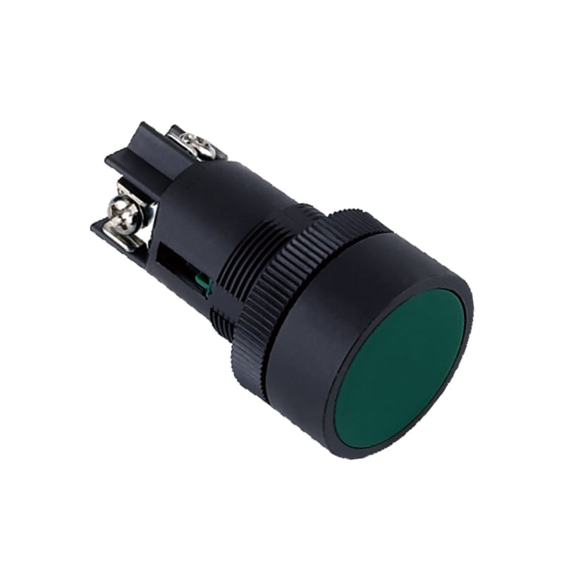
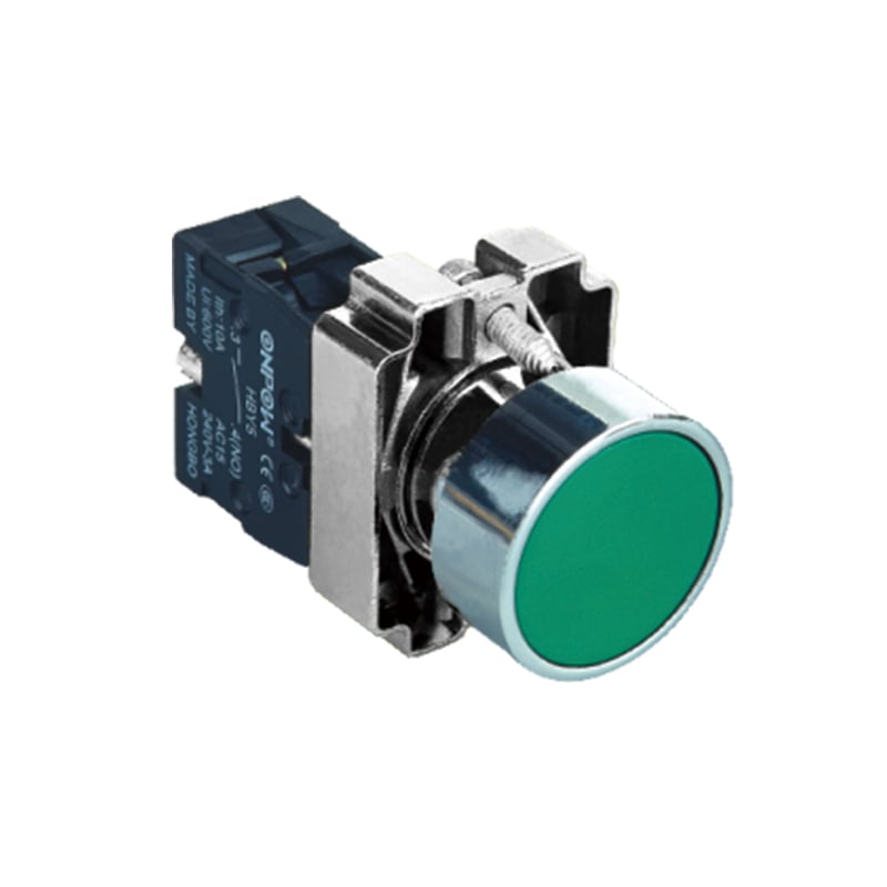
The ONPOW LAS1GQ screw-terminal ring-LED product page is a relevant starting point for a mechanical illuminated panel operator. Its appearance is not evidence of compatibility with a particular PLC. Send the exact input-module diagram, intended contact action, input current conditions, lamp requirements, panel drawing and target environment when requesting a matching configuration.
Ask for the complete order code and terminal drawing, including any internal connections. Request confirmation of the applicable signal duty rather than asking only whether the switch is “24 V.” That phrase can refer to illumination, control voltage or a circuit nominal value, and those are different questions. Preserve the approved response with the sample and the cabinet documentation.
Before placing a production order, test the selected sample with the intended module and released configuration. Record the component identities, measured conditions, expected states and observed results. This creates a repeatable acceptance reference for replacements without claiming that one sample establishes every environmental or lifetime requirement.
Sıkça Sorulan Sorular
Is a mechanical push button a sourcing or sinking device?
İzole edilmiş mekanik temas pasiftir. Güç kaynağı, giriş alma ve ortak bağlantı akış yolunu belirler. Tam montajı kontrol edin çünkü enerjili elektronik anahtarlar veya dahili bağlantılı göstergeler farklı davranabilir.
Giriş tipi iki temas telini ters çevirerek değiştirebilir miyim?
Yalıtılmış pasif bir temas üzerindeki telleri ters çevirmek, modülün iç giriş devresini değiştirmez. Gerekli akım yolunu belirlemek için üreticinin diyagramını ve onaylı konfigürasyonu kullanın.
Does a working LED prove that the PLC input works?
No. Lamp operation and contact signaling can be separate circuits. Confirm the input channel indication and monitored controller state during authorized commissioning.
Is a high contact current rating sufficient for a PLC input?
No. Verify the actual signal duty, any minimum applicable load, input thresholds and installation conditions. A maximum rating alone does not establish reliable low-current switching.
Daha fazla bilgi edinin
Sinking and sourcing input circuits for the current-path section; educational background, not approval of an ONPOW configuration.
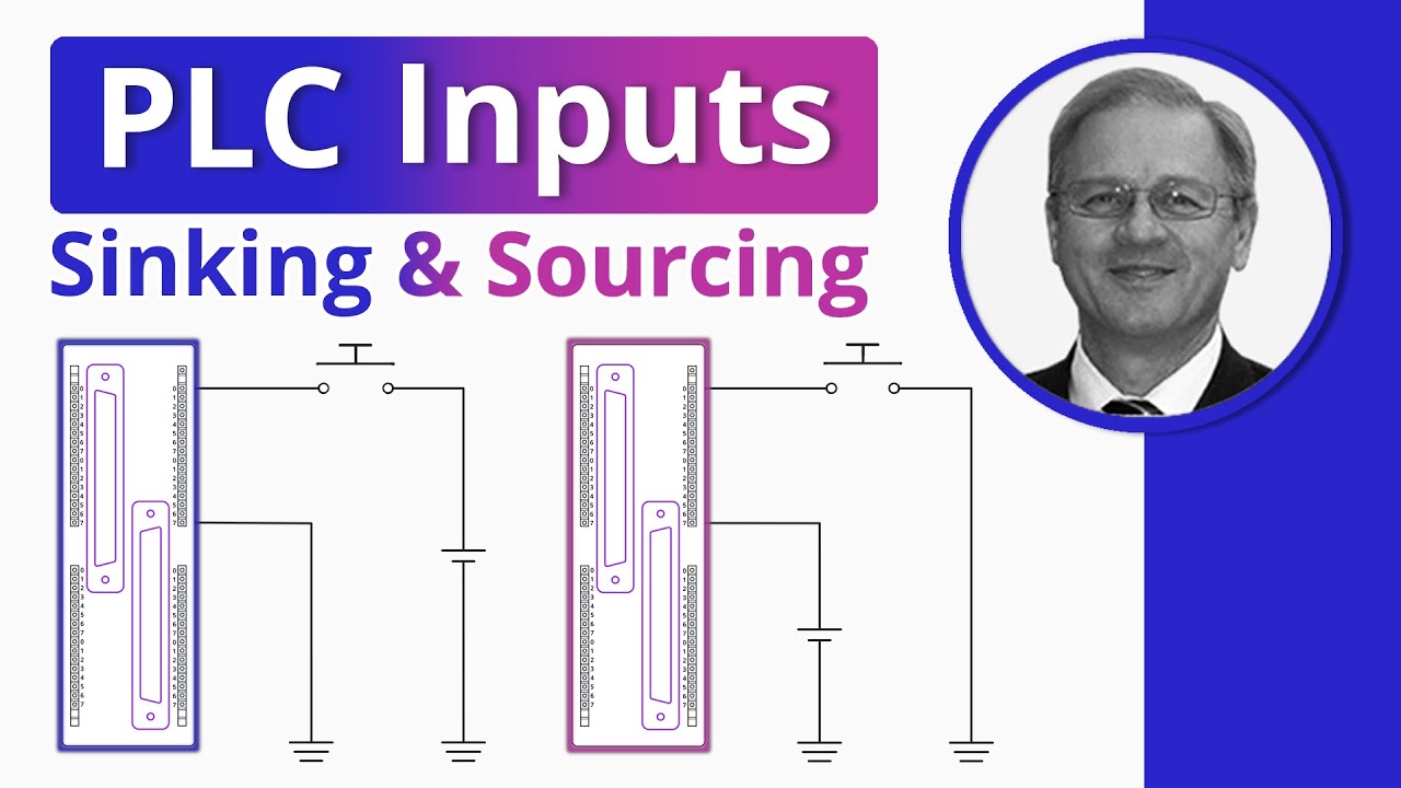
Sinking and Sourcing PLC Inputs Explained | What is the Difference? — RealPars



