

12V vs 24V illuminated push button switches must be specified from the LED circuit first, then from the switching contacts. A 12V lamp option is not a 24V lamp option with a different label: match the documented lamp supply to the selected voltage variant, and confirm the terminal diagram for the exact part number.
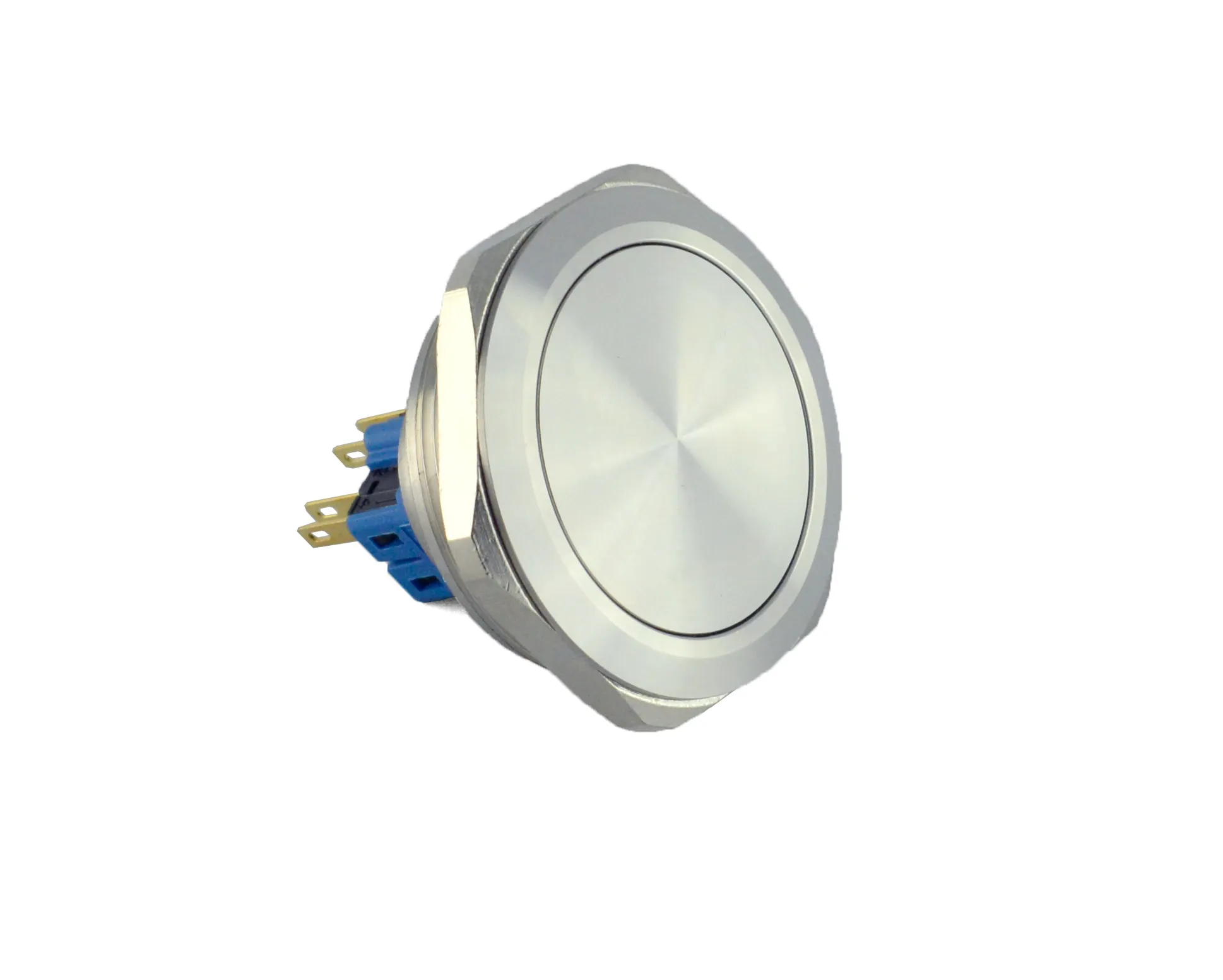
Part 1. What changes between a 12V and 24V illuminated push button?
The change is in the illumination supply specification, not automatically in the contact function. An illuminated push button combines an operating mechanism with a lamp assembly, so a drawing needs to identify both circuits before a panel builder assigns terminals.
ONPOW’s GQ product page lists 6V, 12V and 24V LED options. That page also says that 6–24V versions use internal resistance; its note applies to the GQ family and does not prove the construction of an unlisted SKU.
| Field | 12V LED option | 24V LED option | Procurement effect |
|---|---|---|---|
| Lamp supply to document | 12V | 24V | Match the order code to the actual lamp circuit |
| Contact circuit | Separate specification | Separate specification | State load voltage, current, and load type independently |
| Brightness expectation | Per the selected model | Per the selected model | Do not compare brightness across voltage variants without data |
| Safe shortcut | None | None | A terminal count is not a wiring diagram |
Part 2. Which circuit is the lamp circuit and which circuit switches the load?
Unlike the visible actuator, the contact circuit and the LED circuit often serve different jobs. The contact pair makes or breaks a command or load path; the lamp circuit indicates availability, state, or an operator action.
The NKK illuminated pushbutton guide describes isolated LED circuits and the need for external current limiting when the source exceeds the lamp rating. Treat that as a general design principle, then follow the terminal markings and datasheet for the selected ONPOW part.
Important: Never infer a lamp-terminal connection from the contact rating. The IEC 60947-5-1 publication covers control-circuit devices, but it does not replace the model-specific wiring diagram.
Part 3. How should an LED be wired for power, status, or actuation feedback?
For a power-present indication, the LED circuit is connected across the appropriate control supply so the actuator is lit whenever that supply is available. For state indication, the lamp circuit is driven from a proven auxiliary contact, output, or logic signal that represents the desired state rather than merely a button press.
An actuation-feedback arrangement uses the contact state to energize the lamp only while the intended command path is active. That arrangement must still respect the lamp voltage and any isolation or suppression requirements in the panel design.
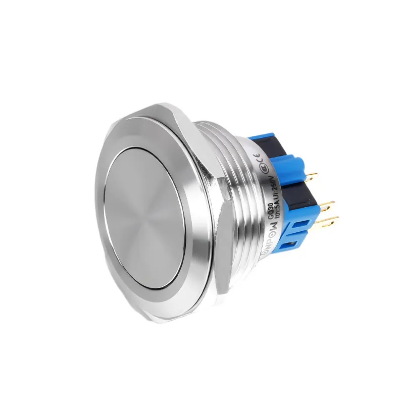
| Desired indication | Circuit decision | What the drawing must show |
|---|---|---|
| Power available | Lamp across the documented control supply | LED voltage option and lamp terminals |
| Command active | Lamp driven by a verified state signal | source of the state signal and common reference |
| Press feedback | Lamp energized through the intended contact logic | whether the action is momentary or latching |
| Fault or remote state | Lamp driven by controller/relay logic | polarity or AC/DC requirement and failure behavior |
Part 4. When do polarity, AC/DC marking, and internal resistance change the design?
If a datasheet marks LED positive and negative terminals, maintain the stated polarity and do not assume a reverse connection is harmless. ONPOW’s GQ page specifically describes an AC/DC LED lamp with no anode/cathode terminal difference; that published note should be used only for the relevant GQ configuration.
At a higher source voltage than a lamp assembly is rated for, current limiting must be designed from verified electrical data. The engineering discussion in Electronics Stack Exchange’s pushbutton LED Q&A highlights why a datasheet may list several voltage variants rather than one interchangeable LED.
Part 5. Which voltage-mismatch mistakes should stop a panel build?
A 12V lamp option connected directly to a 24V supply is a stop condition unless the selected model documentation explicitly supports the arrangement. A 24V option on a 12V supply is also not a specification shortcut: visible output and behavior cannot be accepted from assumption.
Avoid these recurring errors:
– ordering by contact voltage while omitting LED voltage;
– using an external resistor calculation when the internal circuit is unknown;
– tying a status lamp to a contact that does not represent the machine state;
– assuming every illuminated device is polarity-free; and
– treating an AC/DC marking on one series as a universal rule.
Part 6. Which ONPOW illuminated families fit a documented LED specification?
For a project whose lamp circuit is already documented, the ONPOW GQ product family is a relevant starting point because the page publishes 6V, 12V and 24V LED options. It should be narrowed by cutout, operation, terminal type, protection need, LED color, and the exact lamp-circuit note.
The ONPOW61 series lists 16 mm, 19 mm and 22 mm installation diameters, 1NO1NC or 2NO2NC contact structures, and AC/DC 6V/12V/24V/110V/220V LED options. Its published Ui 250V and Ith 5A are series facts, not an instruction to use a contact circuit as the LED supply.
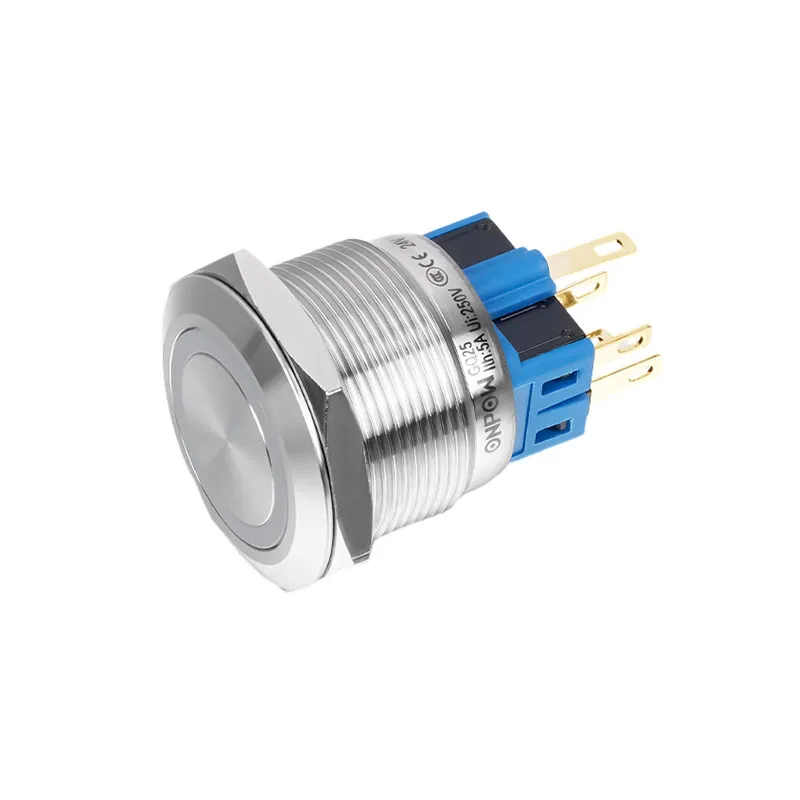
Part 7. What should buyers place in an illuminated push-button RFQ?
An RFQ becomes comparable when it separates the lamp circuit from the switching duty. Send the exact panel cutout, part number if known, momentary or latching action, contact arrangement, contact load and load type, lamp supply, LED color, desired indication behavior, terminal preference, protection target, quantity, and destination-market documentation request.
Fit Boundary: This guide fits projects with a documented low-voltage LED supply and a released circuit concept. It does not fit a retrofit where terminals, supply voltage, or the desired lamp behavior are unknown. Use contact ONPOW with panel specifications after those fields are available, or review the 22mm push button switch guide when cutout selection is still open.
FAQs
What is the difference between a 12V and 24V illuminated push button?
A 12V or 24V label usually identifies the specified lamp supply option. Select it from the actual LED circuit and confirm the exact model’s terminal and resistance information.
Can I connect a 12V illuminated switch to a 24V control circuit?
Not directly by assumption. Stop and use the manufacturer documentation for the selected lamp circuit; a voltage mismatch can require a documented current-limiting solution or a correct voltage variant.
Are the LED terminals separate from the switch contacts?
They often are, but terminal arrangement is model-specific. Use the exact wiring diagram rather than counting pins or relying on another series.
Can the LED stay on when the button is not pressed?
Yes, when the lamp circuit is wired to a suitable documented supply or status signal. The intended behavior must be shown on the schematic.
Do illuminated push buttons always have polarity?
No. Some models are polarity-sensitive while the ONPOW GQ page describes an AC/DC lamp construction without anode/cathode difference. Confirm the selected SKU.
When should I use an external resistor?
Only when the selected lamp documentation requires current limiting for the available source. Do not add or omit a resistor based only on the switch’s appearance.
What must an RFQ state for an illuminated push button?
State the contact duty and lamp circuit separately, plus cutout, action, contacts, LED voltage and color, desired indication behavior, terminals, protection need, quantity, and documentation requirement.



