

Push button switch debouncing prevents one mechanical press or release from being interpreted as several rapid electrical transitions. The contacts inside a physical switch can make and break briefly while they settle; a fast controller may register those changes as multiple input events. A PLC, microcontroller, or external logic circuit can filter the input, but the right method and time depend on the switch, input hardware, signal path, and required response. There is no universal debounce time that is safe for every button or machine.
Begin by distinguishing contact bounce from electrical noise, loose terminals, a damaged contact block, or an application that reads the input repeatedly. Measure or observe the signal at the relevant input, check the controller’s built-in filter options, and test both press and release behavior. ONPOW’s GQ22-L-11E/S push button example shows one panel-button form; confirm the exact contact block, wiring, and control requirements for the model you order. The wider push-button range includes other operator interfaces.
What contact bounce looks like at a controller input
A mechanical button does not always transition from open to closed in one perfectly clean edge. When the contacts meet, small mechanical rebounds can cause a short series of state changes before the contact settles. A digital input may see several transitions even though the operator pressed the button once. Contact bounce can occur on both press and release, and different switches or samples of the same product can behave differently.
The input’s response also matters. Some controllers sample slowly or include an input filter; others use interrupts or high-speed input logic that can react to short transitions. A signal that is harmless for a slowly polled status input can be a problem for a counter, edge-triggered routine, or event queue. Texas Instruments’ switch-debounce application brief describes how physical switches can create false triggers at logic inputs and why a filter may help. Its component example is not a specification for an ONPOW switch or a PLC module.
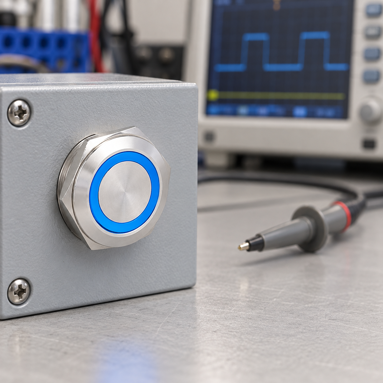
Confirm that bounce is the actual fault
Before adding a delay, check what the system is doing. Look at the raw digital input state, the program’s edge-detection logic, and the output action. If a single press creates multiple transitions at the input, contact bounce or electrical noise may be involved. If the raw input is stable but the machine responds more than once, the issue may be in software logic, task scheduling, or a repeated command path instead.
Other symptoms can resemble bounce:
- Electrical interference: switching loads, long parallel runs, poor shielding, or a grounding issue can disturb the input. A filter may hide a symptom without correcting the wiring cause.
- Loose or worn contacts: intermittent behavior that changes when the panel is touched or vibrated may indicate a terminal, connector, or switch fault.
- Wrong input reference: a sourcing/sinking mismatch, missing common, or unsuitable pull-up can leave the input floating or inverted.
- Application logic: code that counts every scan with the input high can register a long press many times even when the electrical transition is clean.
Use an oscilloscope or suitable logic instrument at a safe, accessible low-voltage signal point when the design permits. Compare raw contact/input behavior with the controller’s interpreted state. Never attach a grounded probe to an unknown or mains-referenced circuit; use appropriately rated isolated measurement equipment and qualified personnel where required.
Choose a debounce method that fits the input
Debouncing can be performed in software, by a PLC’s input filter, or in hardware. These methods have different tradeoffs. A firmware filter can be easy to adjust, while a hardware filter can act before an interrupt or controller scan. A PLC input filter may already be part of the module. The chosen method must preserve short but valid presses and meet the response time the machine needs.
| Method | Where filtering occurs | Useful when | Check before use |
|---|---|---|---|
| Software state stabilization | Application code accepts a state after it remains unchanged for a defined interval | A controller program can tolerate the added response time | Test press and release, task timing, short presses, and repeated events |
| PLC/module input filter | Input hardware or configuration filters transitions before the program reads them | A PLC input provides a documented, configurable filter | Use the exact module manual; confirm how filter settings affect response and fast inputs |
| RC plus Schmitt-trigger logic | Analog edge shaping and hysteresis condition the signal before digital logic | A hardware filter is appropriate and component tolerances are understood | Verify input thresholds, rise/fall behavior, leakage, and minimum pulse width |
| Dedicated interface or safety-rated function | A designed module handles the input condition | The application requires a qualified interface or a safety-rated architecture | Use the exact device instructions and validate the complete machine function |
For a simple software method, a controller can record a candidate state and accept it only after repeated samples remain consistent for the configured interval. A state-change routine can then create one event rather than reacting to every scan while the button stays held. The threshold must be measured and validated; copying a fixed delay from an Arduino example or another machine can make an industrial control feel sluggish or miss a short command.
For a hardware RC filter, the resistor and capacitor shape the edge, and a Schmitt-trigger input provides hysteresis. TI’s application brief shows one such approach and discusses selecting a time constant for the relevant switch behavior. The values shown there apply to that circuit and logic family, not every controller input. Microchip’s AN1450 delay/debouncer note demonstrates a device-specific logic implementation. Use those sources to understand methods, then check the actual input thresholds and component limits for your design.
Set the filter from measured behavior and the required response
Do not choose a debounce time only because it is a common number on a forum. Establish the shortest legitimate press the operator or process must detect, then measure the contact behavior across representative switches and test conditions. Include both opening and closing, since bounce can differ between the press and release edges. Select a filter that rejects the observed transients while still recognizing a valid brief command.
Testing should cover more than a single new switch. Consider multiple samples, operating temperature, mounting, vibration, cable length, input wiring, and the controller’s scan or sample interval where applicable. A filter that works at the bench may behave differently once the actual harness, module, and machine are connected. Keep the chosen setting in the electrical or software documentation so it can be reviewed during service.
For event counting or rapid operation, check whether debounce creates unacceptable latency or suppresses real pulses. A human-operated start command and a high-speed encoder are not the same signal source. Use the controller’s high-speed input or a purpose-built interface when the required event rate exceeds the ordinary input path. If bounce persists after reasonable filtering, inspect the physical switch and wiring rather than increasing the delay indefinitely.
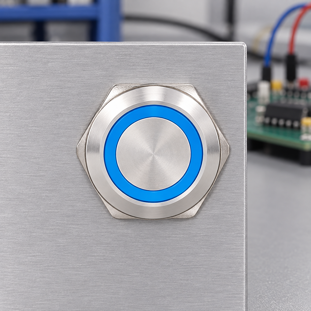
Commission the button and controller together
The panel switch, contact block, wiring, input module, and program form one interface. Confirm the NO/NC contact arrangement from the exact product documentation, then check how that contact maps to the controller’s electrical input type. For context on contact labels and wiring, see the existing push-button installation and wiring guide و 4-pin push-button wiring article. Neither a front photo nor a color ring establishes the terminal map for an assembled operator.
During commissioning, record raw input transitions, filtered input states, and resulting commands for one press and one release. Test a deliberate short press, a long press, rapid repeated presses at the required rate, and recovery after a power cycle if relevant. Confirm that the machine executes each valid command once and that no command is lost. Ask an operator to use the installed control in the real position and check that the response remains clear and timely.
Do not add a general-purpose software delay to an emergency stop, guard interlock, or other safety function. Safety-related controls require an appropriate safety-rated architecture and validation against the machine risk assessment and applicable requirements. IEC 60204-1 covers electrical equipment of machinery, but a debounce setting by itself does not make a circuit safe. Follow the machine builder’s approved design and qualified safety engineering process.
Frequent debouncing mistakes
Filtering without observing the input. First determine whether the multiple transitions are present electrically or introduced by program logic.
Using a large fixed delay everywhere. A long window can make a control feel unresponsive or miss valid short presses. Use measured behavior and the required event timing.
Filtering only the press edge. Release bounce may also create extra events. Test both directions and verify the controller’s chosen method.
Using a capacitor without checking the input. Slow edges, leakage, input thresholds, and hysteresis can change how a controller reads the signal. Follow the component and module documentation.
Treating a failing contact as a software problem. A loose terminal, damaged contact block, contamination, or interference may require a physical repair, not more filtering.
Debouncing a safety circuit with ordinary code. A general-purpose timer is not a safety-rated function. Use the designed safety device and validated architecture.
فيديو تعليمي
This short maker tutorial demonstrates software debounce for a microcontroller pushbutton. It is useful for seeing the basic “one physical press, one logical event” idea, but its controller and timing are examples only. They do not specify a setting for a PLC or ONPOW push button.
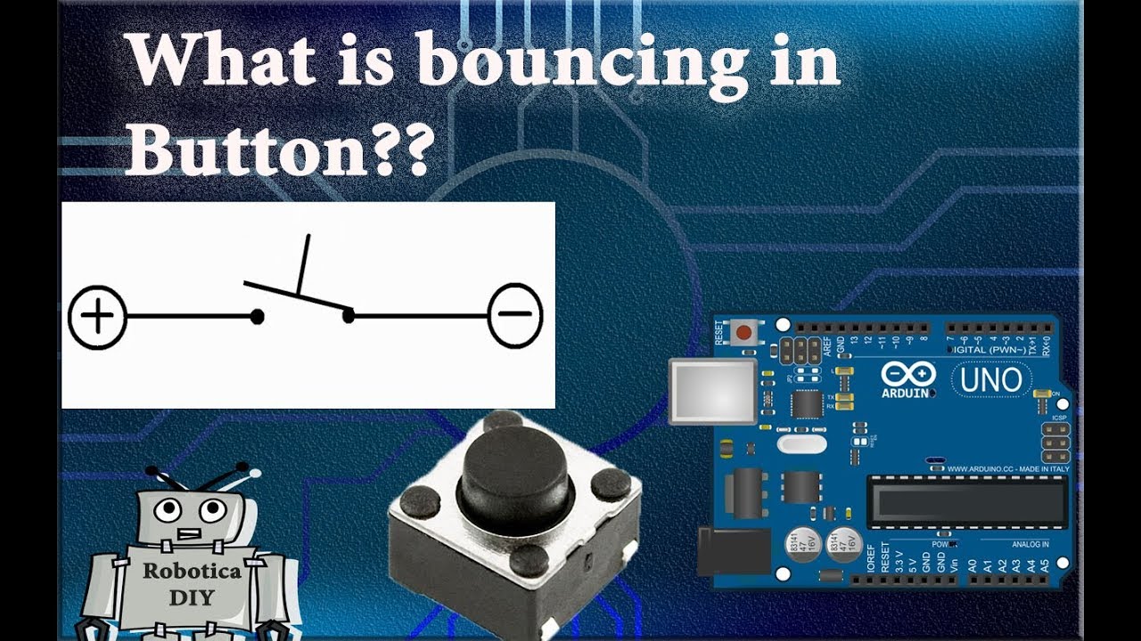
Watch the microcontroller pushbutton debounce example.
الأسئلة الشائعة
Does every push-button switch need debouncing?
No. The need depends on the switch, input module, application logic, and response requirements. Check the raw input and module documentation before adding a filter.
Can contact bounce happen when the button is released?
Yes. Press and release behavior can differ, so validate both edges and ensure the chosen software or hardware method handles the event the machine needs.
What debounce time should I use for a PLC input?
There is no universal value. Use the module’s documented filter range, measure representative switch behavior, and confirm that the resulting delay does not hide a valid short command.
Does a larger RC capacitor always improve debounce?
No. A larger time constant can slow response, affect logic thresholds, and suppress valid events. Check resistor/capacitor tolerances, input leakage, hysteresis, and the controller’s specified edge requirements.
Should an emergency stop be debounced in ordinary PLC code?
No general-purpose debounce setting should be substituted for a validated safety design. Use the designated safety-rated devices and controller architecture defined by the machine’s risk assessment.
المراجع
- Texas Instruments: Debounce a Switch (SCEA094)
- Microchip AN1450: Delay Block/Debouncer
- IEC 60204-1: Safety of machinery — electrical equipment of machines



