

Relay contact arcing happens when current continues to cross the small gap that forms as contacts separate. Inductive loads such as solenoids and motors can raise the voltage across that gap and make the arc harder on the contact surfaces. The right response is not to add a generic diode to every relay. First identify whether the energy is in the relay coil or in the switched load, then confirm the AC or DC circuit, the relay’s application rating, and the suppression method with the device documentation. This guide explains those distinctions and gives a safe review checklist. It is not a substitute for a qualified electrical design or machine-specific validation.
What happens at opening contacts
The current path does not always stop at the instant a relay’s moving contact begins to lift. A very small contact gap can still support an electrical discharge. The arc heats and erodes the contact material. Repeated operations can roughen the contact surface, transfer material from one contact to the other, increase resistance, or eventually prevent a reliable open or closed state. The degree of wear depends on the circuit and the relay. It is not possible to predict service life from the presence of a visible spark alone.
Contact motion, load current, load voltage, switching phase, inrush, frequency of operation, and the relay’s contact construction all matter. A relay selected for a resistive load cannot be assumed to have the same life while switching a motor, lamp bank, transformer, or solenoid. National Instruments explains the relationship between circuit inductance, opening contacts, and arcing. Use that as a general explanation, not as a rating for a different relay model. Read National Instruments’ technical note on arcing.
Arcing and contact welding are also different failure modes. An arc is a discharge across an opening gap. Welding can occur when the contacts overheat or fuse together, including during a high inrush event when they close. A circuit that opens normally at a small test current may still fail under its real load. That is why suppression is only one part of application review; contact selection, load behavior, and operating duty must be checked together.
Separate contact arcing from coil back-EMF
A relay has at least two electrical paths to think about: the coil circuit that moves the armature, and the contact circuit that switches the load. Suppression fitted across the coil limits the coil’s turn-off transient. It protects the coil driver or control electronics, but it does not automatically clamp the voltage at the load contacts. A second suppression component might be needed at the load or contact circuit, depending on the schematic and the equipment design.
The reverse confusion is also common. A contact-side snubber does not automatically protect a transistor or PLC output that drives a DC relay coil. Confirm what each component is connected across before interpreting what it protects. A wiring diagram and the exact relay datasheet are more reliable than wire color, a product photo, or the appearance of a suppression component.
A simple diode across a DC coil is not a universal answer for contact arcing. It can limit the coil’s voltage spike, but it may also change the coil’s release behavior. If release timing affects the load contacts, the designer must assess that effect. Do not move a diode to the contact circuit or change its polarity based on a generic diagram. For AC coils, a single rectifier diode is not an appropriate substitute for a bidirectional or AC-rated solution. The relay manufacturer’s documentation and the control circuit design govern.
Why load type and current matter
An inductive load stores energy in a magnetic field. When current is interrupted, the circuit needs a path or a device that can manage the resulting transient. The voltage and current waveform depend on the load, wiring, and switching device. A DC solenoid, an AC contactor coil, a transformer, and a motor do not have identical transients. Even two motors can differ with supply, mechanical load, operating point, and circuit layout.
Capacitive loads create another problem. A charged capacitor can produce an inrush when contacts close. Adding an RC network or another suppression component may reduce one transient while creating a separate closing-current, leakage, heat, or release-time consideration. Review both closing and opening behavior.
Also distinguish the relay’s electrical life from its mechanical life. A product specification may state a contact rating for a resistive load while listing a separate mechanical endurance value. Neither number by itself promises the same life when switching an inductive or capacitive load. The exact utilization category, load type, switching frequency, ambient conditions, and suppression arrangement have to match the intended application.
Compare suppression approaches
The table below is a screening aid, not a wiring instruction. It helps identify what a designer needs to investigate before selecting a component. The current path, normal and transient voltage, component ratings, stored energy, leakage, and product instructions must be checked for the exact circuit.
| Situation to identify | Approach that may be evaluated | Trade-off or check |
|---|---|---|
| DC coil transient on the coil side | Coil suppression specified for the relay and its driver | Check polarity, coil type, driver rating, and any change to release time |
| DC inductive load switched by contacts | A suitable diode, TVS, or other load-side protection may be evaluated | Check polarity, transient clamp level, load release behavior, and component energy rating |
| AC inductive load switched by contacts | An AC-rated MOV, bidirectional transient suppressor, or RC network may be evaluated | Check leakage current, capacitor safety class, inrush, resistor dissipation, and load behavior |
| Resistive load with acceptable measured life | No added suppression may be appropriate | Confirm contact life and switching conditions rather than adding parts by habit |
Texas Instruments’ discussion of inductive-load turn-off distinguishes a clamp at the switch, a clamp at the load, and a freewheeling path. Those are different circuit locations, not interchangeable part names. The note addresses semiconductor power switches; use it to understand the energy path, not as an ORJ relay contact-rating or snubber-sizing approval. Read the TI inductive-load turn-off application brief.
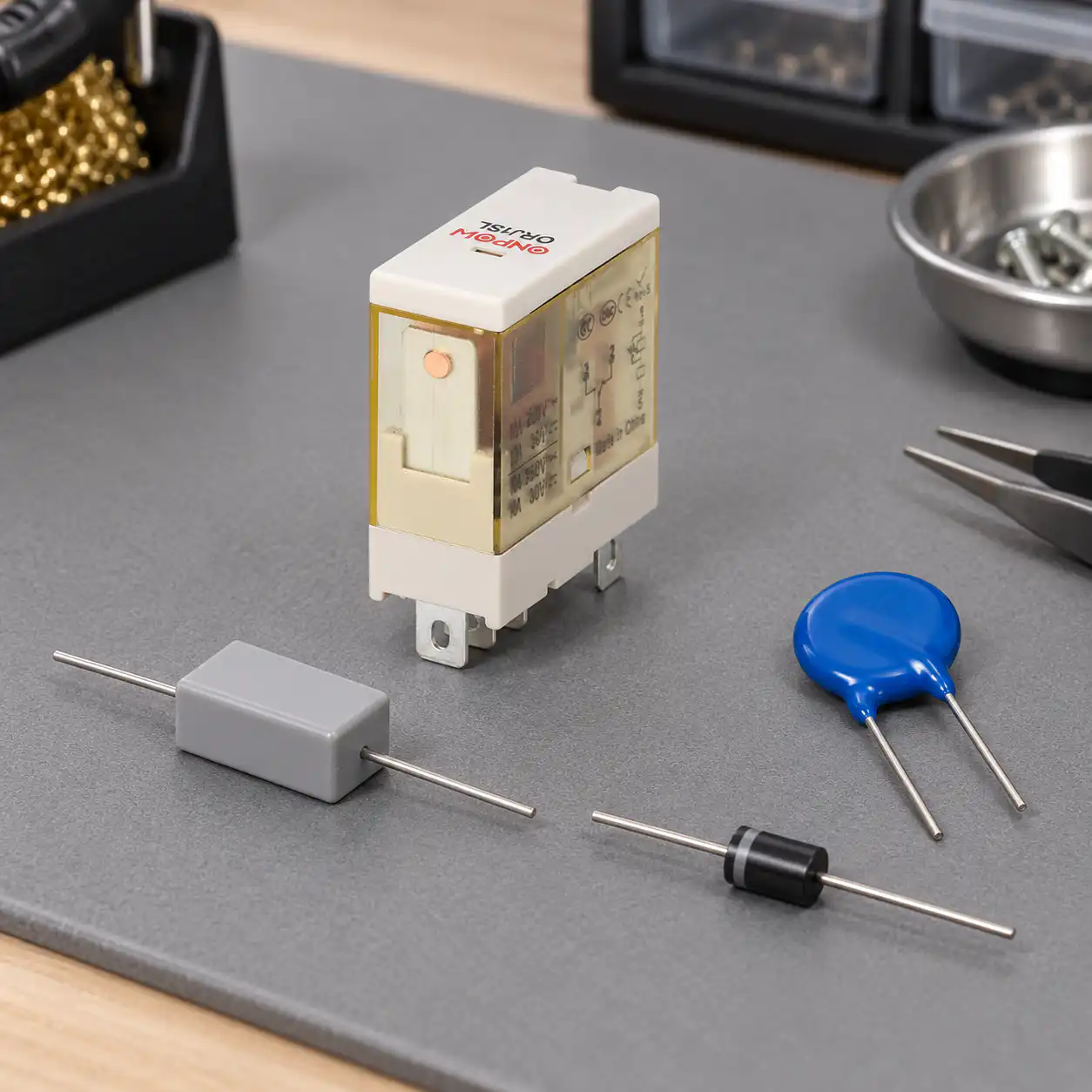
Placement changes the circuit
An RC network across the opening contact and an RC network across the load may both be called a snubber, but they do not create identical circuit behavior. A network across the contact can provide a current path while the relay is open. A network across the load avoids that path through the open contact, but wiring and source impedance can affect how well it suppresses the transient. Any residual current that keeps a lamp, input, or coil partially energized may create a functional problem even when the relay itself appears to operate.
Consider the load’s off-state requirements, the controller input, contact leakage, switching frequency, and component dissipation. When the load position changes, its inductance may change. A suppression network that works on a bench may behave differently with longer wiring, an actual motor, or a different operating cycle. Manufacturers’ notes can suggest methods, but they cannot replace testing on the intended assembly.
A diode, MOV, TVS, or RC network should be selected and placed only by someone who understands the circuit and the applicable component ratings. Do not copy a component value from a forum post, a different voltage, or an unrelated relay board. If waveform measurement is required, use qualified personnel, properly rated equipment, and the site’s electrical safety process.
A review checklist before changing the circuit
- Identify the relay model, coil type, contact diagram, and exact circuit drawing.
- Identify whether the transient is at the coil, the switched load, or both.
- Record AC or DC, steady-state current, inrush or stored energy, switching rate, and expected load release behavior.
- Read the relay and load manufacturers’ documents for the intended load category. Do not equate a resistive rating with an inductive rating.
- Choose an engineering evaluation path for suppression placement, leakage, closing current, component voltage, and thermal dissipation.
- Verify results on the application, including opening and closing behavior, rather than assuming a smaller visible spark guarantees service life.
- Document the accepted circuit and keep machine-specific validation with the equipment record.
Safety comes first. OSHA 29 CFR 1910.333 says exposed live parts should be de-energized before work unless a defined exception applies. It also states that control devices such as push buttons and selector switches cannot be the sole means of de-energizing equipment. Qualified persons must verify the de-energized condition using suitable test equipment. Follow the applicable local rules and employer procedures; this article is not a lockout/tagout procedure. Read OSHA 1910.333.

For broader application selection, start with the electromechanical relay selection guide. This article focuses specifically on contact arcing and suppression, while the guide covers the complete relay specification.
What the ORJ1SL rating does and does not say
The ONPOW ORJ1SL relay product page lists resistive-load ratings by model arrangement, including 12 A at 250 VAC and 30 VDC for the 1S variant, and 8 A at 250 VAC and 30 VDC for the 2S variant. The page labels these as resistive loads. It does not establish an inductive-load rating by implication. The same product page lists additional characteristics, but the exact delivered version and its datasheet must be checked before design use.
This distinction matters when evaluating relay contact arcing. A contact rating tells only what the stated model and test conditions support. It does not define suppression values, motor duty, or switching life for every field load. If an inductive application is planned, request the contact diagram and applicable load rating for the exact order code, then validate the assembled circuit. Do not use an article, an image, or another product’s relay rating as a substitute.
For the circuit layout, see the electromechanical relay wiring diagram guide. For a disconnected component check, see how to test an electromechanical relay safely.
The IEC’s IEC 61810-1 standard page describes general and safety requirements for electromechanical elementary relays used in low-voltage equipment. The standard’s scope does not remove the need to assess application-specific load conditions. The standard page notes that applications with additional requirements should be assessed under relevant standards for that application.
Často kladené otázky
Why do relay contacts arc when they open?
Current may continue across the small gap as contacts begin to separate. Inductive energy, load current, switching phase, contact geometry, and circuit conditions affect whether an arc forms and how long it persists.
Does a flyback diode protect relay contacts?
A diode across a DC relay coil addresses coil turn-off voltage. It does not automatically protect the relay’s switched-load contacts. Identify the energy source and circuit location first.
Can I use a diode for AC contact suppression?
A single-polarity diode is not a universal AC solution. AC circuits require components and arrangements rated for the waveform and application, such as an appropriate MOV, bidirectional transient suppressor, or RC network when engineering evaluation supports it.
Should an RC snubber always be installed across a relay contact?
No. The circuit may have acceptable life without added suppression, and a snubber can introduce leakage, closing current, dissipation, or release-time effects. Compare the actual application and manufacturer guidance.
Can suppression compensate for a relay that is too small for the load?
No. Suppression cannot turn an unsuitable contact rating into a suitable one. Confirm the exact relay, load category, inrush, switching duty, and application requirements before deciding on protection.

Further viewing: Capacitors to prevent arcing damage to DC relay contacts by Andy Reynolds (TheInfoworks). The video covers a DC contact example; use it as a supplement, not a universal design recipe.



