

Relay contact arcing happens when current continues to cross the small gap that forms as contacts separate. Inductive loads such as solenoids and motors can raise the voltage across that gap and make the arc harder on the contact surfaces. The right response is not to add a generic diode to every relay. First identify whether the energy is in the relay coil or in the switched load, then confirm the AC or DC circuit, the relay’s application rating, and the suppression method with the device documentation. This guide explains those distinctions and gives a safe review checklist. It is not a substitute for a qualified electrical design or machine-specific validation.
What happens at opening contacts
The current path does not always stop at the instant a relay’s moving contact begins to lift. A very small contact gap can still support an electrical discharge. The arc heats and erodes the contact material. Repeated operations can roughen the contact surface, transfer material from one contact to the other, increase resistance, or eventually prevent a reliable open or closed state. The degree of wear depends on the circuit and the relay. It is not possible to predict service life from the presence of a visible spark alone.
Contact motion, load current, load voltage, switching phase, inrush, frequency of operation, and the relay’s contact construction all matter. A relay selected for a resistive load cannot be assumed to have the same life while switching a motor, lamp bank, transformer, or solenoid. National Instruments explains the relationship between circuit inductance, opening contacts, and arcing. Use that as a general explanation, not as a rating for a different relay model. Read National Instruments’ technical note on arcing.
Arcing and contact welding are also different failure modes. An arc is a discharge across an opening gap. Welding can occur when the contacts overheat or fuse together, including during a high inrush event when they close. A circuit that opens normally at a small test current may still fail under its real load. That is why suppression is only one part of application review; contact selection, load behavior, and operating duty must be checked together.
Separate contact arcing from coil back-EMF
A relay has at least two electrical paths to think about: the coil circuit that moves the armature, and the contact circuit that switches the load. Suppression fitted across the coil limits the coil’s turn-off transient. It protects the coil driver or control electronics, but it does not automatically clamp the voltage at the load contacts. A second suppression component might be needed at the load or contact circuit, depending on the schematic and the equipment design.
The reverse confusion is also common. A contact-side snubber does not automatically protect a transistor or PLC output that drives a DC relay coil. Confirm what each component is connected across before interpreting what it protects. A wiring diagram and the exact relay datasheet are more reliable than wire color, a product photo, or the appearance of a suppression component.
A simple diode across a DC coil is not a universal answer for contact arcing. It can limit the coil’s voltage spike, but it may also change the coil’s release behavior. If release timing affects the load contacts, the designer must assess that effect. Do not move a diode to the contact circuit or change its polarity based on a generic diagram. For AC coils, a single rectifier diode is not an appropriate substitute for a bidirectional or AC-rated solution. The relay manufacturer’s documentation and the control circuit design govern.
Why load type and current matter
An inductive load stores energy in a magnetic field. When current is interrupted, the circuit needs a path or a device that can manage the resulting transient. The voltage and current waveform depend on the load, wiring, and switching device. A DC solenoid, an AC contactor coil, a transformer, and a motor do not have identical transients. Even two motors can differ with supply, mechanical load, operating point, and circuit layout.
Capacitive loads create another problem. A charged capacitor can produce an inrush when contacts close. Adding an RC network or another suppression component may reduce one transient while creating a separate closing-current, leakage, heat, or release-time consideration. Review both closing and opening behavior.
Also distinguish the relay’s electrical life from its mechanical life. A product specification may state a contact rating for a resistive load while listing a separate mechanical endurance value. Neither number by itself promises the same life when switching an inductive or capacitive load. The exact utilization category, load type, switching frequency, ambient conditions, and suppression arrangement have to match the intended application.
Compare suppression approaches
The table below is a screening aid, not a wiring instruction. It helps identify what a designer needs to investigate before selecting a component. The current path, normal and transient voltage, component ratings, stored energy, leakage, and product instructions must be checked for the exact circuit.
| Situation to identify | Approach that may be evaluated | Trade-off or check |
|---|---|---|
| DC coil transient on the coil side | Coil suppression specified for the relay and its driver | Check polarity, coil type, driver rating, and any change to release time |
| DC inductive load switched by contacts | A suitable diode, TVS, or other load-side protection may be evaluated | Check polarity, transient clamp level, load release behavior, and component energy rating |
| AC inductive load switched by contacts | An AC-rated MOV, bidirectional transient suppressor, or RC network may be evaluated | Check leakage current, capacitor safety class, inrush, resistor dissipation, and load behavior |
| Resistive load with acceptable measured life | No added suppression may be appropriate | Confirm contact life and switching conditions rather than adding parts by habit |
Texas Instruments’ discussion of inductive-load turn-off distinguishes a clamp at the switch, a clamp at the load, and a freewheeling path. Those are different circuit locations, not interchangeable part names. The note addresses semiconductor power switches; use it to understand the energy path, not as an ORJ relay contact-rating or snubber-sizing approval. Read the TI inductive-load turn-off application brief.
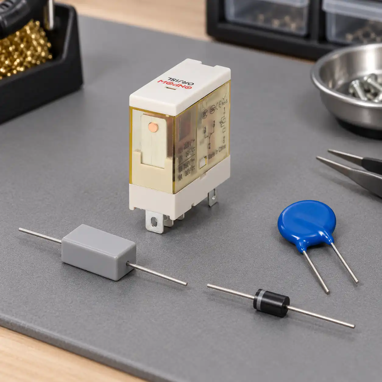
Placement changes the circuit
An RC network across the opening contact and an RC network across the load may both be called a snubber, but they do not create identical circuit behavior. A network across the contact can provide a current path while the relay is open. A network across the load avoids that path through the open contact, but wiring and source impedance can affect how well it suppresses the transient. Any residual current that keeps a lamp, input, or coil partially energized may create a functional problem even when the relay itself appears to operate.
Consider the load’s off-state requirements, the controller input, contact leakage, switching frequency, and component dissipation. When the load position changes, its inductance may change. A suppression network that works on a bench may behave differently with longer wiring, an actual motor, or a different operating cycle. Manufacturers’ notes can suggest methods, but they cannot replace testing on the intended assembly.
A diode, MOV, TVS, or RC network should be selected and placed only by someone who understands the circuit and the applicable component ratings. Do not copy a component value from a forum post, a different voltage, or an unrelated relay board. If waveform measurement is required, use qualified personnel, properly rated equipment, and the site’s electrical safety process.
A review checklist before changing the circuit
- Identify the relay model, coil type, contact diagram, and exact circuit drawing.
- cURL Too many subrequests by single Worker invocation. To configure this limit, refer to https://developers.cloudflare.com/workers/wrangler/configuration/#limits.
- cURL Too many subrequests by single Worker invocation. To configure this limit, refer to https://developers.cloudflare.com/workers/wrangler/configuration/#limits.
- cURL Too many subrequests by single Worker invocation. To configure this limit, refer to https://developers.cloudflare.com/workers/wrangler/configuration/#limits.
- cURL Too many subrequests by single Worker invocation. To configure this limit, refer to https://developers.cloudflare.com/workers/wrangler/configuration/#limits.
- cURL Too many subrequests by single Worker invocation. To configure this limit, refer to https://developers.cloudflare.com/workers/wrangler/configuration/#limits.
- cURL Too many subrequests by single Worker invocation. To configure this limit, refer to https://developers.cloudflare.com/workers/wrangler/configuration/#limits.
cURL Too many subrequests by single Worker invocation. To configure this limit, refer to https://developers.cloudflare.com/workers/wrangler/configuration/#limits. cURL Too many subrequests by single Worker invocation. To configure this limit, refer to https://developers.cloudflare.com/workers/wrangler/configuration/#limits.

より広範な適用選択肢を始めるには、 電気機械リレー選定ガイド.この記事は特に接点のアーキングと抑制に焦点を当てており、ガイドはリレーの完全な仕様をカバーしています。.
What the ORJ1SL rating does and does not say
ONPOW ORJ1SLリレープロダクトページ は、モデル配置別の抵抗負荷定格をリストしており、1Sバリアントでは250VACおよび30VDCで12A、2Sバリアントでは250VACおよび30VDCで8Aを含みます。ページはこれらを抵抗負荷としてラベル付けしています。誘導負荷定格は暗黙のうちに設定されていません。同じ製品ページには追加の特性も記載されていますが、正確な納品バージョンとそのデータシートを設計使用前に確認する必要があります。.
この区別はリレー接点のアーキングを評価する際に重要です。接点定格は、記載されたモデルと試験条件がサポートする内容だけを示しています。抑制値、モーターの運転負荷、スイッチング寿命をすべての現場負荷に対して定義しているわけではありません。誘導性アプリケーションを計画している場合は、正確な注文コードに対する接点図と適用負荷定格をリクエストし、その後組み立てた回路を検証してください。記事や画像、他の製品のリレー定格を代用しないでください。.
回路レイアウトについては、 electromechanical relay wiring diagram guide. を参照してください。 切断されたコンポーネントの確認については、.
電気機械リレーを安全にテストする方法 IECの IEC 61810-1標準ページ.
よくある質問
リレー接点はなぜ開くときにアークが発生するのですか?
接点が離れ始めると、小さな隙間を越えて電流が流れ続けることがあります。誘導エネルギー、負荷電流、スイッチング位相、接点形状、および回路条件によって、アークが発生するかどうか、またその持続時間が左右されます。.
フライバックダイオードはリレーの接点を保護しますか?
DCリレーコイルに並列接続されたダイオードは、コイルの電源遮断時に発生する電圧に対処するものです。リレーの開閉負荷接点を自動的に保護するものではありません。まず、エネルギー源と回路内の発生箇所を特定してください。.
は、低電圧機器で使用される電気機械式基本リレーの一般的および安全要件を記述しています。標準の範囲は、アプリケーション固有の負荷条件の評価の必要性を排除しません。標準ページには、追加の要件を持つアプリケーションは、そのアプリケーションに関する関連標準の下で評価されるべきであると記載されています。
単方向ダイオードは、あらゆるAC回路に対応できる汎用的な解決策ではありません。AC回路には、波形や用途に適した定格を持つ部品や構成が必要です。例えば、適切なMOV(バリスタ)、双方向過渡電圧サプレッサ、または技術的な評価に基づいて適用が妥当と判断されたRCスナバ回路などが挙げられます。.
リレー接点に常にRCスナバーを取り付ける必要がありますか?
いいえ。追加のサージ抑制を行わなくても回路の寿命に問題がない場合があります。また、スナバ回路を追加すると、漏れ電流、投入電流、電力損失、または復帰時間への影響が生じる可能性があります。実際の使用条件とメーカーの推奨事項を比較検討してください。.
抑制は負荷に対して小さすぎるリレーを補うことができますか?
いいえ。サージ抑制を行っても、不適切な接点定格が適切なものに変わるわけではありません。保護方法を決定する前に、リレーの正確な型式、負荷カテゴリ、突入電流、開閉頻度および用途に関する要件を確認してください。.

AC接点抑制にダイオードを使用できますか? Capacitors to prevent arcing damage to DC relay contacts さらに見る:.



