

To test an electromechanical relay, start with its own diagram and the machine’s electrical safety procedure. A basic bench check can compare the coil resistance with the exact model’s published data and confirm whether normally open (NO) and normally closed (NC) contacts change state as expected. Those checks can find an open coil or a contact that does not change, but they do not prove that a relay can safely switch its rated load or meet a machine’s safety function. Isolate the relay before using a meter’s resistance or continuity mode. Do not rely on a push button or PLC command as the only means of de-energizing equipment. If testing requires energized work, it must be done by a qualified person using site-approved procedures and correctly rated test equipment.
First identify the relay and the test boundary
The phrase “test a relay” can refer to very different work. This guide covers a basic inspection of a removable, electromechanical control relay away from its operating circuit. It does not cover protective-relay injection testing, safety-relay validation, high-voltage insulation testing, load-life qualification, or commissioning of a complete machine.
Before removing a relay, record the equipment state and the exact relay model. Photograph or document its wiring, socket position, coil voltage, contact diagram, and any suppression component. A relay with a DC coil and built-in diode, a latching relay, a relay with an indicator module, or a special interface may require a different test. Contact numbers and coil terminals vary between product families, so never identify pins only by appearance or by a diagram from another relay.
ONPOW’s ORJ2SL electromechanical relay is one model example. Its product page gives model-specific ratings and diagrams. Those specifications are not universal thresholds for all electromechanical relays, even when another device has a similar package or pin count.
De-energize the equipment before resistance checks
Do not measure resistance or continuity on a live circuit. For fixed equipment, follow the site’s lockout/tagout and electrical safety procedures. OSHA 29 CFR 1910.333 requires exposed live parts to be de-energized before work unless a defined exception applies, and requires qualified people and suitable safeguards for energized work. Its verification rule calls for appropriate test equipment to verify the actual circuit parts are de-energized. A control push button, selector, PLC command, or interlock by itself is not an energy-isolating device.
This article is not a lockout/tagout procedure and does not authorize energized testing. Identify all energy sources, isolate them, address stored energy, and verify the zero-energy condition under the responsible site procedure. If the relay is part of a safety function, a basic bench test does not validate the safety function or permit the equipment to return to service.
Step 1: inspect the relay and its socket
With the relay removed and the equipment made safe, check for a cracked housing, heat discoloration, damaged pins, loose socket contacts, contamination, corrosion, or an odor suggesting overheating. If the relay is sealed, do not open it to inspect internal contacts. A visible mark may indicate damage, but a clean appearance does not prove the relay is electrically sound.
Check that the socket and terminal labels match the relay’s own diagram. A similar-looking relay can have a different coil voltage, contact arrangement, pinout, or built-in diode. If the relay’s model number or diagram is unreadable, stop and obtain the manufacturer’s documentation before applying power.
Step 2: compare coil resistance with the exact datasheet
Use a meter on resistance only after the relay is removed from any energized circuit and isolated from parallel paths. Identify the two coil terminals from the model diagram, then measure across them. Compare the reading with the exact model’s published coil resistance and stated tolerance at its specified conditions. Do not use one “normal” resistance range for every relay: coil voltage, AC or DC design, temperature, and construction affect the expected value.
An open-circuit reading may indicate a broken coil path. A reading near zero may indicate a short, but first check that the selected terminals are actually the coil and that the meter is connected correctly. A reading within the datasheet range is only a preliminary check. It does not prove that the relay will pull in reliably, release correctly, or switch a real load.
If the relay contains a diode or another electronic component across the coil, the measured result may depend on probe polarity and meter design. Use the product’s documentation. Do not reverse-energize a polarized coil to “see if it works.”
Step 3: check the unpowered contact states
Read the relay diagram to identify common (COM), normally open (NO), and normally closed (NC) terminals. “Normally” refers to the manufacturer-defined normal state for that relay; for a standard non-latching relay, that is commonly the de-energized coil state. A latching relay may retain its last position without coil power, so its current state must be interpreted according to the manufacturer’s instructions.
With the relay unpowered and isolated, measure only the contact pairs specified by the diagram. An expected-closed contact should show continuity within the limits of the test and meter. An expected-open contact should not show continuity. Compare the result to the relay’s diagram and specified contact conditions. Do not infer a pass from a continuity buzzer alone; the meter’s buzzer threshold is not a load-capacity test.
| 確認 | Basic observation | What it can suggest | What it cannot prove |
|---|---|---|---|
| Coil resistance | Matches, open, near-zero, or differs from the model specification | Open coil, possible short, wrong terminals, or a reading affected by temperature/components | Pull-in reliability, release behavior, insulation condition, or remaining life |
| NO contact at rest | Open or unexpectedly conductive | Possible welded/stuck contact, a latching state, wrong terminals, or an incorrect diagram interpretation | Ability to interrupt the intended load |
| NC contact at rest | Closed or unexpectedly open | Possible contact damage, wrong terminals, or a different relay/contact form | Contact resistance under rated load or long-term reliability |
| Change of state on a permitted isolated bench test | Contacts change or fail to change when the rated coil is applied | Basic actuation or release fault | Dielectric strength, electrical endurance, safety function, or load suitability |
Step 4: energize only on a controlled bench when permitted
If the model documentation and your organization’s test procedure permit a coil-actuation test, perform it on a suitable isolated bench setup. Use only the exact rated coil supply and observe polarity when the coil or suppression circuit is polarized. Keep the relay removed from the machine circuit. With the power supply off, connect a low-energy indicator or meter to the documented contact pair, apply the specified coil supply, and confirm that the relay changes state. Then remove the supply and check that the expected return or retained state occurs.
Do not apply mains voltage directly to an unknown relay. Do not select a voltage based on the contact rating; the coil rating is a separate specification. Do not exceed the coil’s permitted voltage or duty time. If the manufacturer has not provided a clear rating or test method, stop and request one instead of improvising a bench procedure.
What a multimeter check cannot certify
A basic resistance and contact-state check is a screening step, not a full relay qualification. It cannot establish contact performance under a real load, electrical endurance, insulation coordination, dielectric strength, switching arc behavior, timing limits, vibration resistance, or suitability for a safety-related control function. IEC 61810-1 defines general requirements and type-test context for electromechanical elementary relays; a field continuity check is not equivalent to those specified tests.
For an intermittent failure, record the machine conditions, coil voltage, load type, ambient conditions, operating frequency, and fault timing. A relay may test correctly at rest but still fail when switching an inductive, minimum, or high-inrush load. Check the circuit, socket, suppression, input/output device, and actual load requirements before replacing the relay. Never increase the relay rating or substitute a different coil voltage based only on a bench result.
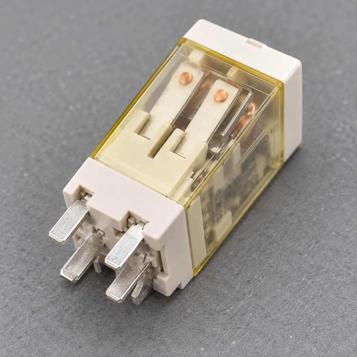
A careful replacement and return-to-service check
If the relay fails a model-specific check, record the model, coil marking, contact form, measured values, and test conditions. Replace it only with an approved part that matches the coil and contact requirements, footprint, pin arrangement, suppression, and documented load. Similar housings can hide important differences.
Before reinstalling, verify the socket condition and terminal mapping. Follow the site procedure for removing locks or tags and re-energizing the equipment. A qualified person should perform the required inspection and functional test for the equipment. Confirm that the machine returns to its intended state and that no safety function depends solely on a general-purpose relay. Keep the replaced relay or its record for failure analysis if the fault was recurring.
For the relay’s terminal functions, see ONPOW’s electromechanical relay wiring diagram guide. The relay selection guide explains how coil, contact, and load requirements affect the specified part. For general contact terminology, review ONPOW’s article on normally open and normally closed switches.
The following video demonstrates a generic multimeter check on an electromechanical relay. The demonstrated pin numbers and examples are not an ONPOW ORJ2SL pinout or an authorization for live work; always use the exact model diagram and site safety process.
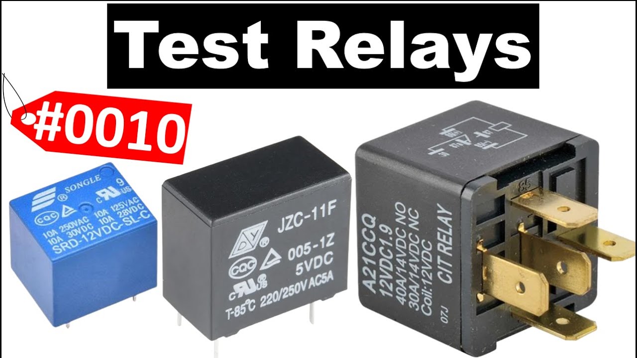
Open the general relay multimeter demonstration on YouTube

よくある質問
Can I test a relay while it is still wired into the control panel?
Do not measure resistance or continuity on energized equipment. For a reliable isolated check, follow the site’s lockout/tagout procedure and remove or electrically isolate the relay as directed. A qualified person must verify de-energization with appropriate test equipment before exposed parts are handled.
What resistance should an electromechanical relay coil have?
There is no universal resistance value. Use the exact relay model’s documentation, including coil voltage, AC or DC type, temperature conditions, and tolerance. If the model or terminal diagram is unknown, do not apply a guessed pass/fail range.
Does a continuity beep prove a relay contact is good?
No. A continuity beep only indicates that the meter detects a path under its test conditions. It does not establish acceptable contact resistance under the real load, switching performance, endurance, or safety-related performance.
Can I apply a different voltage to hear whether the relay clicks?
No. Use only the coil voltage and polarity permitted by the exact model documentation, and only in a controlled, isolated test setup handled by a qualified person. The contact rating is not the coil rating.
Does a basic test prove that a relay is suitable for a safety function?
No. A bench check cannot validate a complete safety function or replace its required design, fault analysis, testing, and maintenance. Follow the machine’s risk assessment, applicable standards, and documented validation procedure.



