

To test an electromechanical relay, start with its own diagram and the machine’s electrical safety procedure. A basic bench check can compare the coil resistance with the exact model’s published data and confirm whether normally open (NO) and normally closed (NC) contacts change state as expected. Those checks can find an open coil or a contact that does not change, but they do not prove that a relay can safely switch its rated load or meet a machine’s safety function. Isolate the relay before using a meter’s resistance or continuity mode. Do not rely on a push button or PLC command as the only means of de-energizing equipment. If testing requires energized work, it must be done by a qualified person using site-approved procedures and correctly rated test equipment.
First identify the relay and the test boundary
The phrase “test a relay” can refer to very different work. This guide covers a basic inspection of a removable, electromechanical control relay away from its operating circuit. It does not cover protective-relay injection testing, safety-relay validation, high-voltage insulation testing, load-life qualification, or commissioning of a complete machine.
Before removing a relay, record the equipment state and the exact relay model. Photograph or document its wiring, socket position, coil voltage, contact diagram, and any suppression component. A relay with a DC coil and built-in diode, a latching relay, a relay with an indicator module, or a special interface may require a different test. Contact numbers and coil terminals vary between product families, so never identify pins only by appearance or by a diagram from another relay.
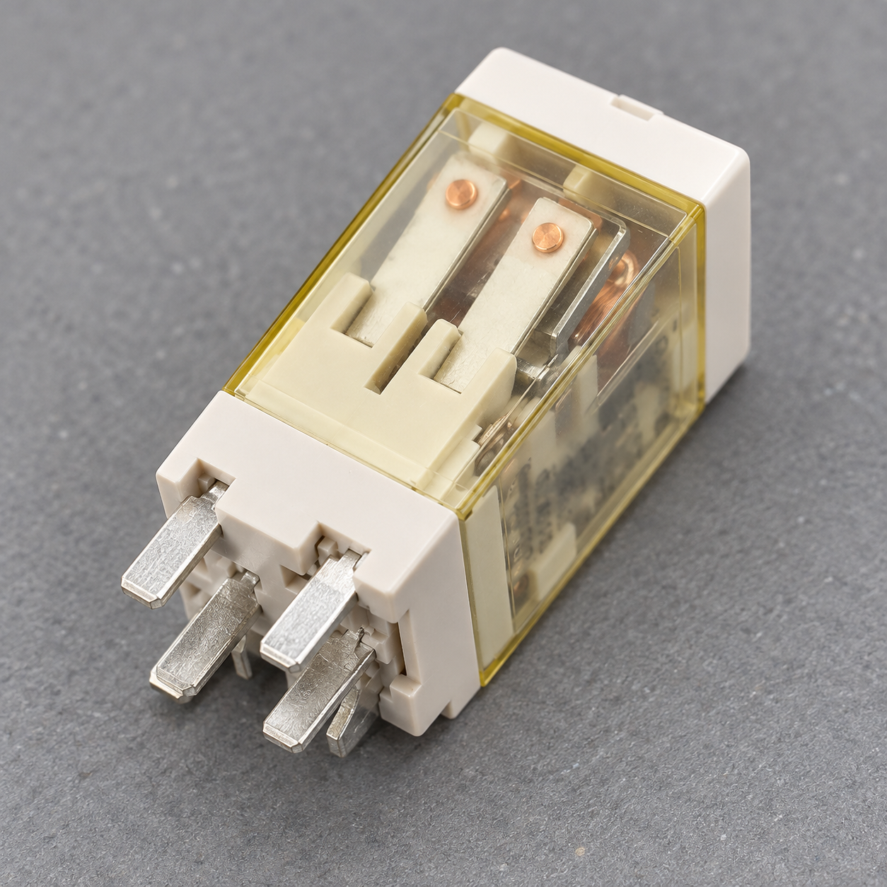
ONPOW’s ORJ2SL electromechanical relay is one model example. Its product page gives model-specific ratings and diagrams. Those specifications are not universal thresholds for all electromechanical relays, even when another device has a similar package or pin count.
De-energize the equipment before resistance checks
Do not measure resistance or continuity on a live circuit. For fixed equipment, follow the site’s lockout/tagout and electrical safety procedures. OSHA 29 CFR 1910.333 requires exposed live parts to be de-energized before work unless a defined exception applies, and requires qualified people and suitable safeguards for energized work. Its verification rule calls for appropriate test equipment to verify the actual circuit parts are de-energized. A control push button, selector, PLC command, or interlock by itself is not an energy-isolating device.
This article is not a lockout/tagout procedure and does not authorize energized testing. Identify all energy sources, isolate them, address stored energy, and verify the zero-energy condition under the responsible site procedure. If the relay is part of a safety function, a basic bench test does not validate the safety function or permit the equipment to return to service.
Step 1: inspect the relay and its socket
With the relay removed and the equipment made safe, check for a cracked housing, heat discoloration, damaged pins, loose socket contacts, contamination, corrosion, or an odor suggesting overheating. If the relay is sealed, do not open it to inspect internal contacts. A visible mark may indicate damage, but a clean appearance does not prove the relay is electrically sound.
Check that the socket and terminal labels match the relay’s own diagram. A similar-looking relay can have a different coil voltage, contact arrangement, pinout, or built-in diode. If the relay’s model number or diagram is unreadable, stop and obtain the manufacturer’s documentation before applying power.
Step 2: compare coil resistance with the exact datasheet
Use a meter on resistance only after the relay is removed from any energized circuit and isolated from parallel paths. Identify the two coil terminals from the model diagram, then measure across them. Compare the reading with the exact model’s published coil resistance and stated tolerance at its specified conditions. Do not use one “normal” resistance range for every relay: coil voltage, AC or DC design, temperature, and construction affect the expected value.
An open-circuit reading may indicate a broken coil path. A reading near zero may indicate a short, but first check that the selected terminals are actually the coil and that the meter is connected correctly. A reading within the datasheet range is only a preliminary check. It does not prove that the relay will pull in reliably, release correctly, or switch a real load.
If the relay contains a diode or another electronic component across the coil, the measured result may depend on probe polarity and meter design. Use the product’s documentation. Do not reverse-energize a polarized coil to “see if it works.”
Step 3: check the unpowered contact states
Read the relay diagram to identify common (COM), normally open (NO), and normally closed (NC) terminals. “Normally” refers to the manufacturer-defined normal state for that relay; for a standard non-latching relay, that is commonly the de-energized coil state. A latching relay may retain its last position without coil power, so its current state must be interpreted according to the manufacturer’s instructions.
With the relay unpowered and isolated, measure only the contact pairs specified by the diagram. An expected-closed contact should show continuity within the limits of the test and meter. An expected-open contact should not show continuity. Compare the result to the relay’s diagram and specified contact conditions. Do not infer a pass from a continuity buzzer alone; the meter’s buzzer threshold is not a load-capacity test.
| Sprawdź | Basic observation | What it can suggest | What it cannot prove |
|---|---|---|---|
| Coil resistance | Matches, open, near-zero, or differs from the model specification | Open coil, possible short, wrong terminals, or a reading affected by temperature/components | Pull-in reliability, release behavior, insulation condition, or remaining life |
| NO contact at rest | Open or unexpectedly conductive | Possible welded/stuck contact, a latching state, wrong terminals, or an incorrect diagram interpretation | Ability to interrupt the intended load |
| NC contact at rest | Closed or unexpectedly open | Possible contact damage, wrong terminals, or a different relay/contact form | Contact resistance under rated load or long-term reliability |
| Change of state on a permitted isolated bench test | Contacts change or fail to change when the rated coil is applied | cURL Too many subrequests by single Worker invocation. To configure this limit, refer to https://developers.cloudflare.com/workers/wrangler/configuration/#limits | cURL Too many subrequests by single Worker invocation. To configure this limit, refer to https://developers.cloudflare.com/workers/wrangler/configuration/#limits |
Step 4: energize only on a controlled bench when permitted
cURL Too many subrequests by single Worker invocation. To configure this limit, refer to https://developers.cloudflare.com/workers/wrangler/configuration/#limits.
cURL Too many subrequests by single Worker invocation. To configure this limit, refer to https://developers.cloudflare.com/workers/wrangler/configuration/#limits.
What a multimeter check cannot certify
cURL Too many subrequests by single Worker invocation. To configure this limit, refer to https://developers.cloudflare.com/workers/wrangler/configuration/#limits.
cURL Too many subrequests by single Worker invocation. To configure this limit, refer to https://developers.cloudflare.com/workers/wrangler/configuration/#limits.
A careful replacement and return-to-service check
cURL Too many subrequests by single Worker invocation. To configure this limit, refer to https://developers.cloudflare.com/workers/wrangler/configuration/#limits.
cURL Too many subrequests by single Worker invocation. To configure this limit, refer to https://developers.cloudflare.com/workers/wrangler/configuration/#limits.
For the relay’s terminal functions, see ONPOW’s Przewodnik po schematach okablowania przekaźników elektromechanicznych. The przewodnik wyboru przekaźników explains how coil, contact, and load requirements affect the specified part. For general contact terminology, review ONPOW’s article on normally open and normally closed switches.
The following video demonstrates a generic multimeter check on an electromechanical relay. The demonstrated pin numbers and examples are not an ONPOW ORJ2SL pinout or an authorization for live work; always use the exact model diagram and site safety process.
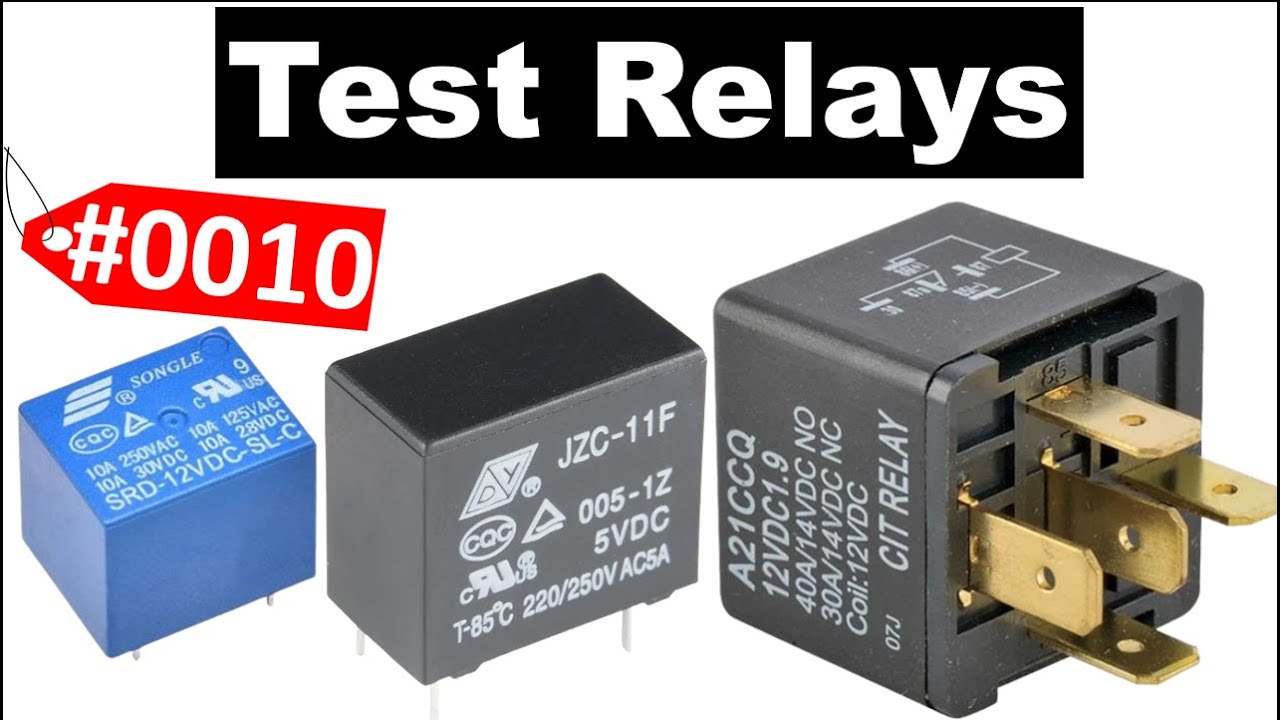
Open the general relay multimeter demonstration on YouTube
Często zadawane pytania
Can I test a relay while it is still wired into the control panel?
Nie należy mierzyć rezystancji ani ciągłości obwodu w urządzeniach znajdujących się pod napięciem. Aby przeprowadzić wiarygodną kontrolę odizolowanego przekaźnika, należy postępować zgodnie z obowiązującą w zakładzie procedurą blokowania i oznakowania źródeł energii (LOTO) oraz wyjąć przekaźnik lub odizolować go elektrycznie zgodnie z zaleceniami. Przed dotknięciem odsłoniętych części osoba posiadająca odpowiednie kwalifikacje musi potwierdzić brak napięcia za pomocą właściwego sprzętu pomiarowego.
Jaką rezystancję powinna mieć cewka elektromagnetycznego przekaźnika?
Nie istnieje uniwersalna wartość rezystancji. Należy korzystać z dokumentacji dokładnego modelu przekaźnika, uwzględniając napięcie cewki, rodzaj prądu (AC lub DC), warunki temperaturowe oraz tolerancję. Jeśli model lub schemat zacisków nie są znane, nie należy stosować zgadywanego zakresu wartości do oceny, czy przekaźnik spełnia wymagania.
Czy sygnał dźwiękowy ciągłości potwierdza, że styk przekaźnika jest dobry?
Nie. Dźwięk sygnalizujący ciągłość obwodu wskazuje tylko, że miernik wykrywa ścieżkę w warunkach testowych. Nie potwierdza to akceptowalnego oporu styków pod rzeczywistym obciążeniem, wydajności przełączania, wytrzymałości ani bezpieczeństwa.
Can I apply a different voltage to hear whether the relay clicks?
Nie. Używaj wyłącznie napięcia i polaryzacji cewki zgodnie z dokumentacją konkretnego modelu, i tylko w kontrolowanym, izolowanym układzie testowym obsługiwanym przez wykwalifikowaną osobę. Obciążenie styków nie jest tym samym co obciążenie cewki.
Does a basic test prove that a relay is suitable for a safety function?
Nie. Kontrola na stanowisku nie może potwierdzić pełnej funkcji bezpieczeństwa ani zastąpić jej wymaganego projektu, analizy awarii, testowania i konserwacji. Postępuj zgodnie z oceną ryzyka maszyny, obowiązującymi normami oraz udokumentowaną procedurą walidacji.



