

Push button switch replacement compatibility depends on the complete assembly and circuit duty, not just the mounting-hole diameter. Compare the original order code with the proposed replacement across action, contacts, electrical ratings, illumination, terminals, mounting and environment. Record every difference and obtain the required engineering approval before installation. A replacement that fits the panel or passes a continuity check can still change the machine’s behavior. This guide provides a whole-device comparison and release workflow; it does not declare cross-brand interchangeability or authorize substitutions in emergency-stop or other safety-related functions.
Establish the original assembly before searching for substitutes
Begin with the equipment drawing, parts list and maintenance history. Record the installed button’s full identity, including suffixes and any separately supplied operator, holder, contact block, illumination module and connector. A product-family name may cover several configurations. If markings are incomplete, preserve photographs and ask the manufacturer or equipment builder to resolve the identity before ordering.
Describe the reason for replacement. A damaged operator, intermittent contact, unavailable spare and planned panel redesign are different situations. If the old assembly failed because the installation was unsuitable, buying an apparently equivalent part may repeat the failure. Record the fault and any known environmental or mechanical changes without assuming that the button itself caused the machine symptom.
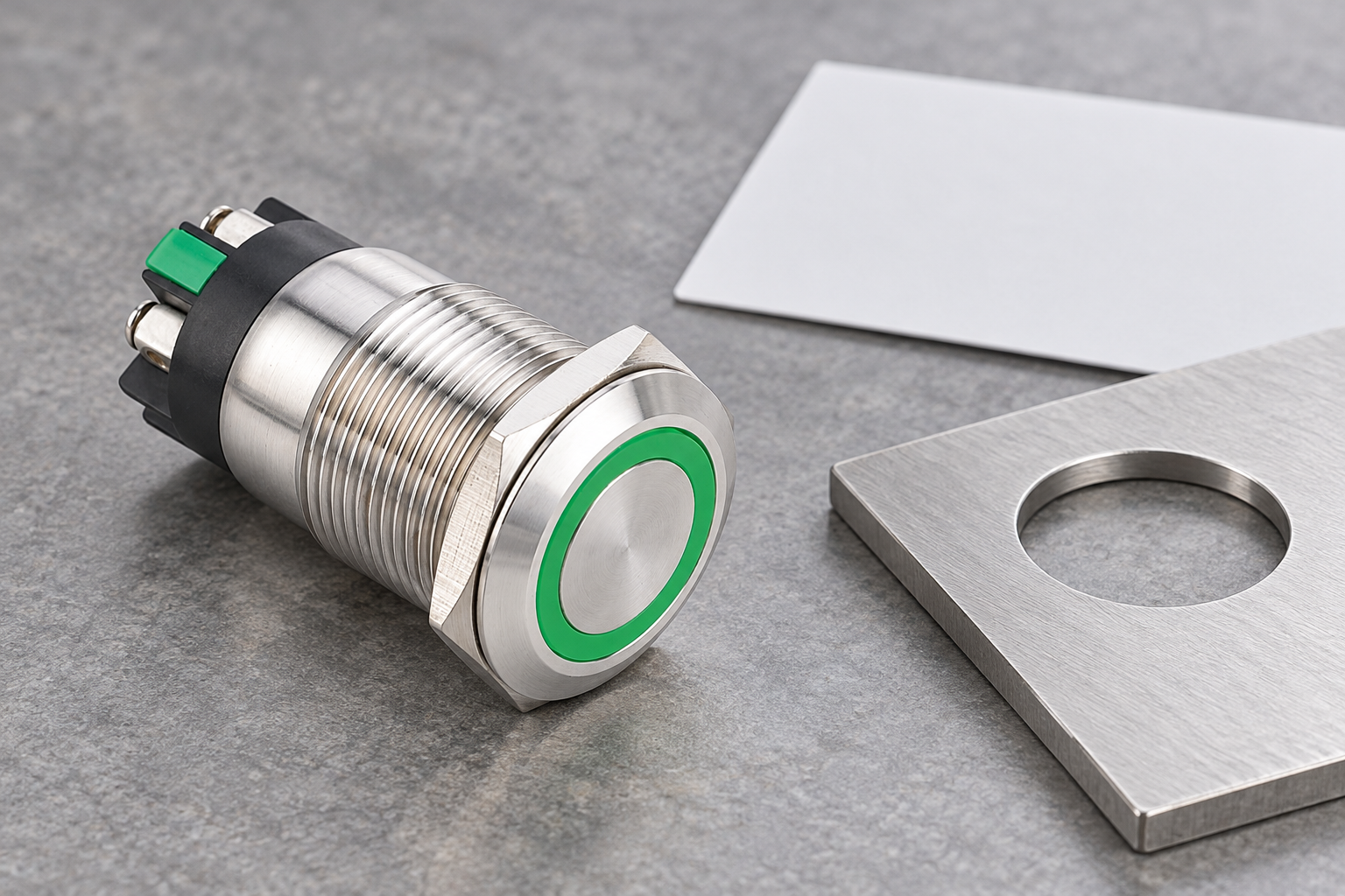
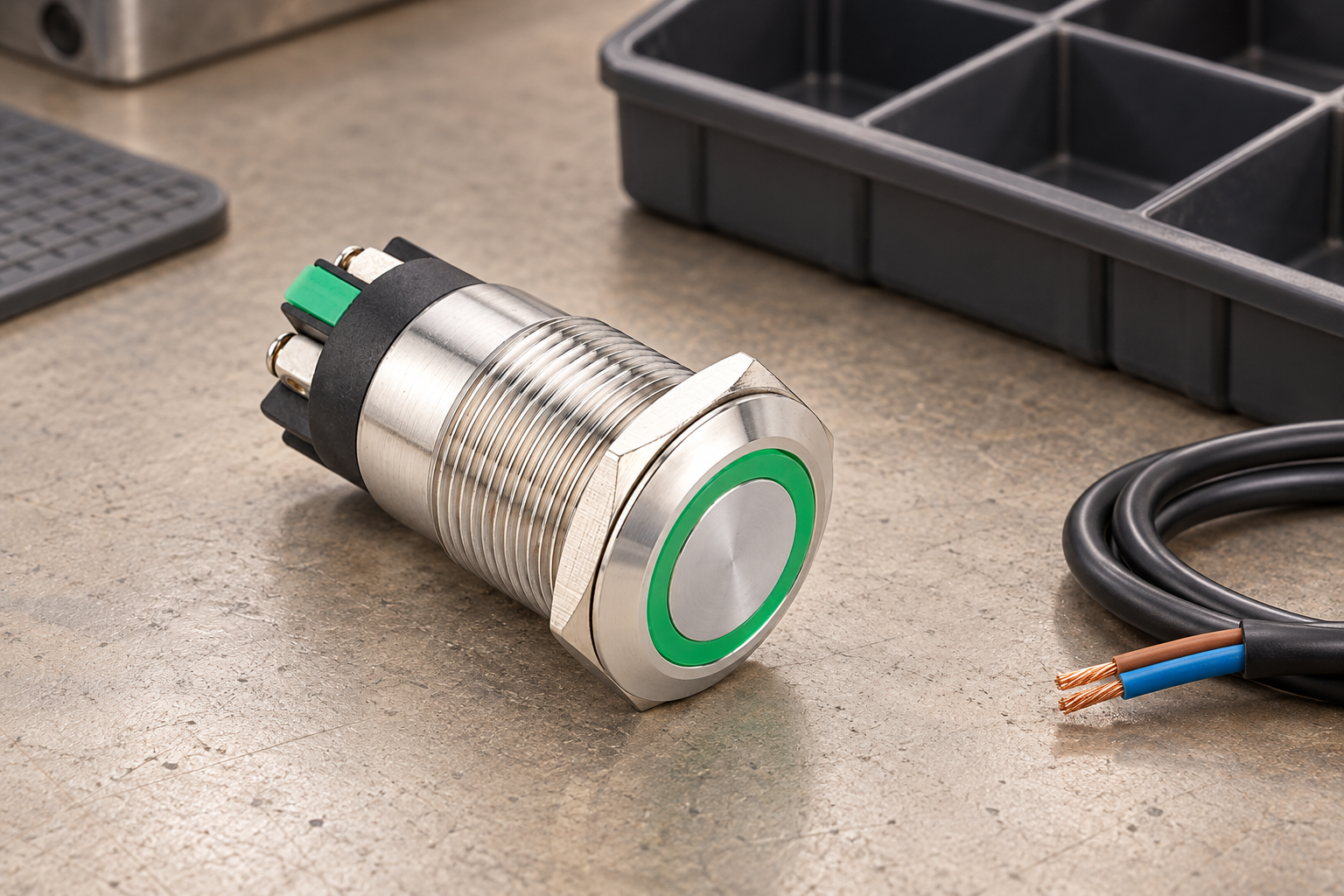
The ONPOW ring-LED screw-terminal push button is an example of a specific product enquiry target. Its front appearance is useful for identification, but compatibility requires the exact model documentation. Do not infer action, contact material, electrical duty or illumination voltage from a green ring or stainless steel head.
Compare operator action and contact behavior
Determine whether the intended control is momentary, maintained or otherwise configured. Record the normal state and the result of actuation, release and any reset action. A maintained substitute can alter a control sequence that expects a momentary command. A similar-looking actuator is therefore insufficient evidence, even when it occupies the same position on the panel.
Compare contact quantity, normal state, common connections and any required contact sequence. Match the circuit function to the documented contact arrangement instead of assigning terminals by their physical position. Terminal numbering can differ between assemblies. Keep the original wire identifiers and an approved terminal-to-terminal mapping as separate records; photographs alone may not show all connections clearly.
Safety-related devices require the equipment’s specific substitution and validation process. A general replacement checklist cannot establish the required safety performance, mechanical action or system compatibility. Hold such a proposal for the responsible designer. Do not downgrade an emergency-stop or protective function to an ordinary control button because the mounting dimensions happen to match.
Build a complete replacement comparison
Use a comparison record with evidence references, not just matching checkmarks. Each item should identify the source document and revision for the original and proposed parts. Missing information is a review item, not an assumed match. The table below is qualitative; numerical ratings and tolerances must come from the actual parts and circuit documentation.
| Comparison area | Original requirement to capture | Replacement evidence | Difference requiring review |
|---|---|---|---|
| Operator action | Command on press, release and reset | Exact configuration description | Momentary versus maintained action |
| Kontakty | Normal state, quantity and sequence | Contact table and terminal drawing | Different mapping or switching sequence |
| Electrical duty | Actual circuit voltage, current and load | Ratings for the applicable duty | Only an unrelated maximum rating matches |
| Osvětlení | Supply, polarity and intended meaning | Lamp specifications and wiring information | Different lamp supply or connection |
| Installation | Cutout, panel stack, depth and locating features | Dimension drawing and assembly instructions | New interference or changed seal arrangement |
| Prostředí | Exposure and maintenance conditions | Product limits and application approval | Missing evidence for cleaning or installation |
| Release | Required machine verification and authorization | Approved test record | Unresolved behavior or documentation change |
Use the record to decide whether the proposed part is an equivalent replacement or an engineering change. A difference does not automatically make a part unusable, but it prevents an unsupported claim that the substitution is direct. The decision should remain traceable to the person authorized to approve it.
Check electrical duty beyond the headline current
Read the circuit requirement and product rating together. The voltage, AC or DC supply, load characteristics, switching frequency and required life can matter. A larger headline current does not prove suitability for the actual control load. The proposed part must be qualified for the relevant application rather than ranked by a single number on a distributor page.
Low-energy inputs need particular attention. A replacement may satisfy a maximum rating while lacking evidence for the required signal duty. The separate minimum switching load guide addresses that question. Confirm any manufacturer limits and application validation conditions; do not copy numerical limits from a different switch family or a competing manufacturer’s example.
If a measurement is part of acceptance, define what it proves. A continuity beep can identify a contact state on an appropriately isolated sample, but it does not establish all electrical performance or endurance. Specify the approved method, instruments, sample conditions and acceptance criteria. Hold an uncertain result instead of increasing test energy or repeatedly operating the device until it appears satisfactory.
Treat illumination as a separate compatibility check
An illuminated button combines an operator function with an indication function. Identify the actual lamp supply, permitted voltage, AC or DC requirements, polarity where relevant and terminal arrangement. Match the intended indication meaning as well. A green light that now follows a command instead of confirmed equipment state can change how operators interpret the machine.
Použít push button polarity guide when separating contact behavior from the illumination branch. Do not assume that every terminal belongs to the same circuit. Nor should a replacement’s connector pin count be used as a universal wiring diagram. Obtain the exact connection information for both assemblies before making a mapping.
If the proposed lamp characteristics differ, document the interface review with the controller output or power supply. This article provides no universal resistor, polarity or driver recommendation. An accepted replacement should have its indication checked under the approved equipment test plan, including the intended normal, commanded and fault conditions where the application requires them.
Verify the installed envelope and connection method
Compare the finished cutout, panel thickness range, anti-rotation features, seal arrangement and assembly hardware. Two products sharing a nominal mounting diameter can have different locating requirements or rear clearances. Do not enlarge or reshape the existing opening as an informal maintenance adjustment. Such work needs the appropriate panel drawing and change approval.
Review the space behind the panel with the actual harness. A shorter switch body may still create a difficult wire bend if its terminals point in a different direction. Check service access and any moving-door route. The panel thickness and mounting stack guide covers the clamping interface; compatibility also requires enough space for connections and authorized maintenance.
A change from screw terminals to solder or plug connections is a process change as well as a part change. It may require different tools, conductor preparation, harness parts and inspection records. Confirm the permitted conductor and connector conditions for the replacement. Do not reuse an old mating part merely because it appears to latch onto the new assembly.
Preserve the enclosure and maintenance boundary
Compare the environmental conditions of the installed assembly, including the front interface and rear location. A component’s protection designation applies under its specified conditions; it does not automatically transfer to an altered panel. The IEC 60529 publication provides the enclosure-protection framework, while the actual product documentation establishes the relevant installation requirements.
Check cleaning, temperature and other exposure conditions separately. A material or finish change can require a new cleaning review even when the product’s nominal protection designation is unchanged. The equipment’s maintenance documentation should identify the accepted conditions and any restrictions. Avoid broad promises that a replacement is “more waterproof” or “more durable” without comparable evidence.
The installation work itself needs a safe plan. HSE’s electrical equipment work guidance addresses planning and secure isolation. Use competent personnel and the equipment’s authorized procedure. Removing a control device is not an opportunity to improvise energized fault-finding or bypass an interlock to keep production moving.
Validate the replacement and update the controlled records
Before return to service, verify the installed identity, mounting, wiring mapping, operator action and indication against the approved plan. Perform the required machine-response checks under controlled conditions. The person releasing the repair should be able to connect the test result to the exact replacement and equipment revision. An informal statement that “it works” is not a useful long-term record.
Record any differences that were accepted and the basis for approval. Update the parts list, wiring documentation, spare stock information and maintenance instructions as required. Clearly distinguish an approved substitute from a candidate awaiting review. Otherwise, an unapproved trial part can enter the purchasing system and be ordered repeatedly as though it were established stock.
For an ONPOW compatibility enquiry, send the original complete code, proposed model, circuit duty, contact table, lamp supply, panel drawing and photographs. Ask for written clarification of component capabilities and differences. The equipment owner or responsible designer must then approve the application and release process. A well-prepared comparison makes that decision faster and reduces guesswork during the repair.
For the wider installation context, see the push button panel design guide. Its layout and verification principles complement this article; the specific acceptance criteria still belong to the approved equipment documentation.
Často kladené otázky
Does the same mounting-hole size mean a direct replacement?
No. Check the complete mounting arrangement, action, contact behavior, electrical duty, illumination, terminals and environmental conditions. A matching nominal diameter proves only one part of the comparison.
Is a higher current rating always a better substitute?
No. The rating must apply to the actual circuit conditions, and low-energy signal duty may need separate evidence. Compare the relevant specifications rather than choosing by the largest current value.
Can an illuminated button be wired by matching terminal positions?
Do not assume terminal positions are equivalent. Use the exact contact and lamp connection drawings and an approved mapping. Contact and illumination circuits can have different requirements.
Can this checklist approve an emergency-stop substitution?
No. Emergency-stop and other safety-related substitutions require the equipment’s specific engineering approval and validation. This general checklist helps organize information but cannot establish system safety compatibility.
Further learning
University lecture on inspection, testing and quality control, supporting the documented replacement acceptance process. It does not establish a model-specific interchangeability claim.



