

A yellow push button can help an operator notice a condition or action, but colour is only one part of a control-panel message. The function should be clear from the nearby label or symbol, the machine state, the control narrative, and the project’s applicable requirements. Define those elements before selecting a yellow operator or adding it to a panel drawing.
Part 1. Define what a yellow push button communicates—and what it does not
Yellow is commonly used in panel design to draw attention, often where an operator should notice an abnormal condition or use a specific intervention. That description is deliberately conditional. The physical colour does not carry a complete, universal instruction by itself.
A yellow operator should never force an operator to guess whether it starts, stops, resets, acknowledges, tests, or changes a machine state. The meaning is established by the surrounding HMI design and the documented control philosophy. It is also unsafe to infer an emergency-stop function merely from a yellow button.
| Input around a yellow control | Por qué importa | No infieras |
|---|---|---|
| Nearby text or symbol | Gives the intended action a readable name | That yellow alone explains the action |
| Machine state | Explains when the control may be used | That it is always a start or stop command |
| Risk assessment and instructions | Aligns the control with the intended protective strategy | That colour replaces safety design |
| Project colour convention | Creates consistency across the machine | That every market uses one identical meaning |
El IEC 60073 publication covers coding principles for indicators and actuators. Use applicable editions and local rules with the machine documentation rather than copying a single colour convention without context.
Part 2. Link colour to a nearby label, symbol, and machine state
The strongest panel message combines a visible control, a concise label or recognized symbol, and behaviour that matches what the operator sees on the machine. A yellow control used for a fault acknowledgement, for example, should have a clear legend and an understandable condition in the control logic. If the function changes by operating mode, the documentation and HMI should make that change visible.
Importante: Do not use a yellow push button as the sole explanation of an action. The IEC 60447 resource addresses actuator principles; the final function, legend, and placement should be checked against the project’s machine-control documentation.
Keep wording short enough to be read at the operating position. Avoid generic labels such as “RESET” if the action can have several consequences; use the approved machine terminology. Where a pictogram is used, confirm that it matches the operation and is legible after the panel finish, lighting, and viewing angle are considered.
For a broader discussion of colour as one layer of the interface, see the push button color coding guide. That supporting article does not replace the project-specific label review described here.
Part 3. Keep operator controls distinct from indicator lights
An illuminated push button can combine a manually operated actuator with light output, while a pilot light is primarily an indication device. On a busy panel, users should be able to distinguish “press this” from “observe this” without studying the wiring diagram. Shape, label, location, and illumination behaviour all contribute to that distinction.
Do not assume that an illuminated yellow cap has the same message as a separate yellow indicator. A flashing pattern, steady light, and momentary or maintained operator action can each carry different implications. Define the function in the I/O list and the control narrative before choosing the hardware configuration.
El ring versus dot LED illumination guide is useful when the selected control needs an illuminated form. Confirm illumination voltage, lens style, wiring, and operation for the actual SKU rather than applying a category image as a specification.
Part 4. Place yellow controls where an abnormal-condition action is understood
Place a yellow operator near the related machine information and within the reach path used for that action. A control that acknowledges a condition should not be separated from the relevant status display or placed where it can be confused with a normal run command. Consistent spacing and label alignment make this relationship easier to understand.
IEC 61310-3 addresses the location and operation of actuators. In a practical review, check viewing angle, gloved use, accidental-operation exposure, and whether another nearby control has a similar appearance. A colour choice is more useful when the surrounding layout reinforces the same message.
| Panel review element | Question to resolve | Design impact |
|---|---|---|
| Location | Can the operator see the relevant state before pressing? | Reduces ambiguous action |
| Label | Is the action readable and unambiguous? | Supports training and troubleshooting |
| Adjacent controls | Could another button be pressed by mistake? | Improves spacing and grouping |
| Illumination behaviour | Is steady, flashing, or off state defined? | Keeps indication consistent |
| Operating mode | Does the control mean the same thing in every mode? | May require mode-specific indication |
For a panel-wide placement review, use the push-button control panel layout guide. The final decision should remain tied to the machine’s approved design package.
Part 5. Record operator characteristics before selection
Once the function and meaning are defined, create a short selection record. This helps prevent a visually suitable yellow part from being ordered with the wrong cutout, action, contacts, terminal direction, or illumination arrangement. It also gives suppliers the context needed to review a proposed SKU.
| Selection record to share | Why the supplier needs it | What it controls |
|---|---|---|
| Function and exact label | Confirms the intended human action | Legend and operating form |
| Panel cutout and thickness | Checks mechanical mounting | Body, nut, and gasket fit |
| Momentary or maintained action | Matches control logic | Operator mechanism |
| Contact and circuit requirement | Prevents a visual-only selection | Contact configuration review |
| Illumination requirement | Defines the visible state | Lens and voltage options |
| Destination and quantity | Frames documentation and supply review | Quotation and delivery planning |
Colour should be written as one confirmed characteristic, not the entire requirement. If the control is part of a protective function, send the relevant safety and control documentation for review. Do not substitute a colour statement for electrical or functional verification.
For an RFQ, share this complete selection record with the controlled panel drawing so the proposed configuration can be checked against the intended function.
Part 6. Use ONPOW metal push-button options through a confirmed-SKU review
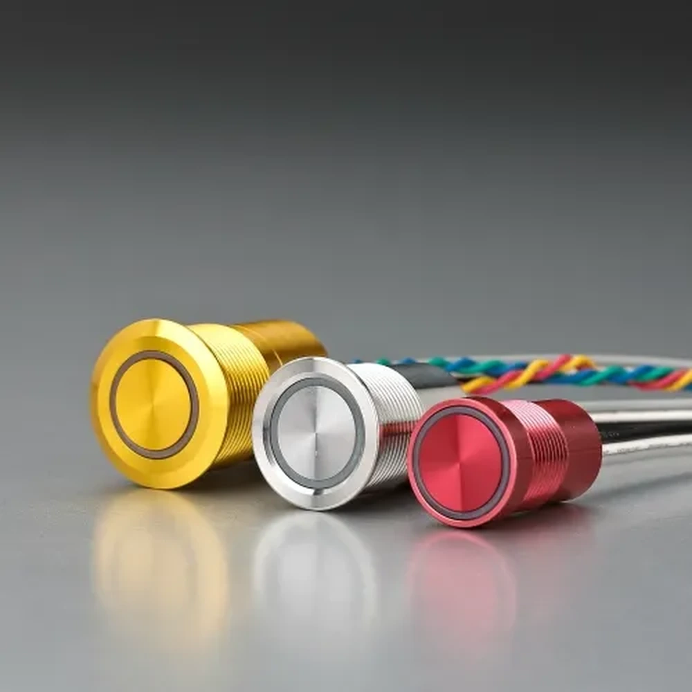
When the label, placement, cutout, and action are controlled, use the ONPOW metal push button switch category as a route to discuss available product families. Ask ONPOW to confirm the chosen SKU’s colour, mounting dimensions, operator action, contact arrangement, terminal option, illumination fields, and applicable documentation. A category page alone does not establish any of those model-specific properties.
Include the control drawing, label artwork, panel material and thickness, required quantity, and destination in the enquiry. Explain the intended machine state that the yellow control represents. That gives the technical review enough context to identify an appropriate configuration without reducing the decision to a paint colour.
For more selection resources, visit the Blog de ONPOW. Retain the approved colour legend and control narrative with the panel’s released manufacturing data.
Preguntas Frecuentes
What does a yellow push button mean?
It can be used to attract attention or support an abnormal-condition action, but the actual meaning must be defined by the label, symbol, machine context, and project requirements. It is not a universal instruction by itself.
Is a yellow button always a reset button?
No. A yellow operator may be used for different documented functions. Use an explicit label and the approved control narrative to define the action.
Can I use yellow for an emergency stop?
Do not infer an emergency-stop function from yellow alone. Emergency-stop design, identification, and suitability must follow the applicable machine-safety requirements and the approved design documentation.
Should a yellow illuminated push button replace a pilot light?
Not automatically. An illuminated push button is an actuator with light output, while a pilot light is primarily an indicator. Choose the form that makes the required operator action and machine state clear.
What information should be on the panel drawing?
Show the exact label or symbol, location, cutout, panel thickness, intended operator action, illumination behaviour, and relevant circuit or I/O reference. Add any operating-mode dependency.
How do I request a yellow ONPOW push button?
Send the controlled panel drawing and selection record to ONPOW. Ask for confirmation of the selected SKU’s colour, cutout, action, contacts, terminals, illumination options, and documentation.



