

An LED tower-light wiring diagram shows how the light modules, any buzzer, the supply, and the controller outputs fit together. Before wiring, identify the exact model and whether the control output sources current or sinks it. “Common positive” and “common negative” describe circuit topologies in some DC systems; they are not universal wire colors, and they do not replace the product’s terminal diagram.
For example, ONPOW’s HBJD-40/40A wiring guide gives model-specific light leads and common wires. It distinguishes HBJD-40 from HBJD-40A, including separate common leads for steady and intermittent functions on the latter. Do not transfer those assignments to a different tower-light model. This guide explains how to read the wiring logic and how to verify it against the order code. The HBJD-40A three-tier product page is one model example; the broader multilevel warning-light range includes different layer and sound configurations.
Identify the exact tower-light configuration
Start with the full model code, the supply marked for that version, the number and order of light tiers, and whether sound is included. A single-layer indicator, a three-layer tower, and a five-layer tower can share similar housings but use different leads and control options. A suffix may change the function, voltage, mounting style, or sound behavior.
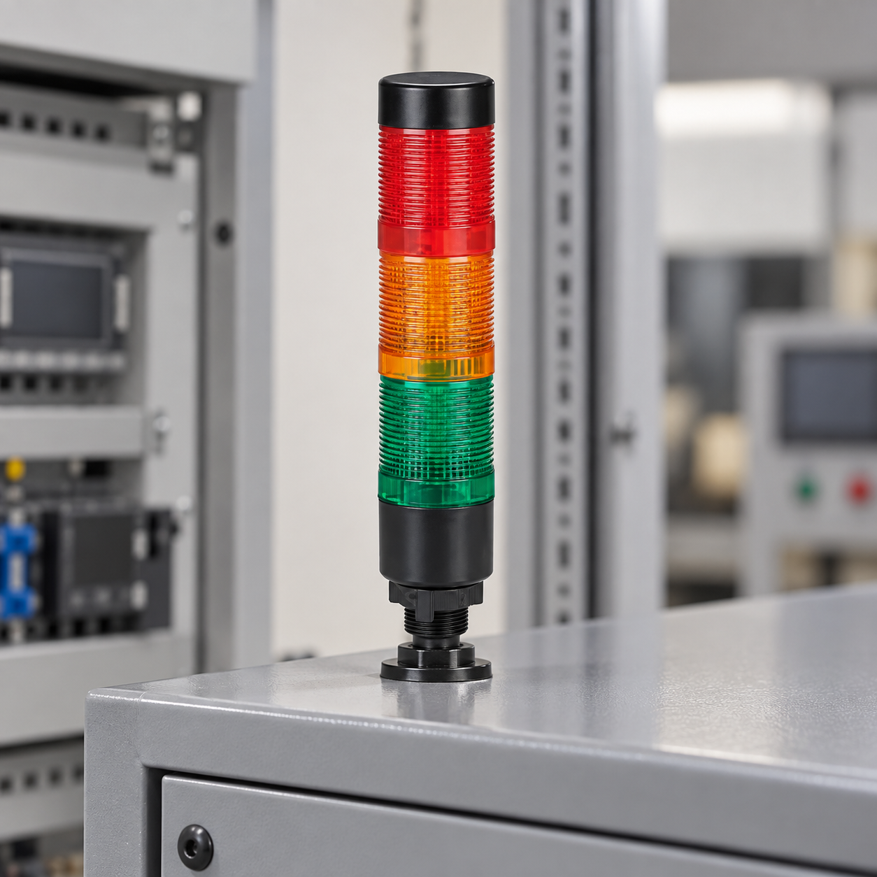
Read the wiring diagram supplied for that model. Map every control lead, common lead, supply lead, and buzzer lead from the drawing to the physical cable or terminal block. The lens colors visible from the front tell you which states the operator can see; they do not tell you the electrical lead assignment.
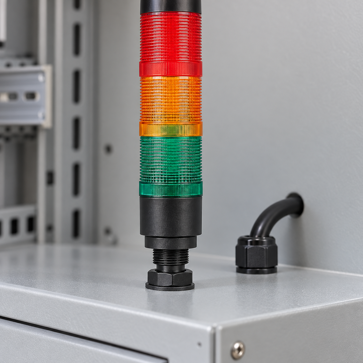
The tower in the photo below is an indoor panel installation. It is not a universal wiring layout for every multicolor signal lamp.
Common-positive and common-negative describe the circuit path
The meaning of “common positive” or “common negative” depends on the device and drawing. In a general DC output circuit, a sourcing output provides the positive potential to the load when active; the load returns to the supply’s 0 V side. A sinking output provides the return path toward 0 V; the load is connected to the positive supply. National Instruments’ industrial digital I/O guidance describes these output types for specific hardware and illustrates why the exact module documentation determines the connection.
Do not translate that explanation into a wire color. A tower-light assembly may use a shared common conductor, multiple common conductors for different functions, a separate supply lead, or an AC/DC version. The ONPOW HBJD-40 manual identifies the black lead as a common wire for that model. The HBJD-40A drawing uses different common leads for its steady/continuous and flashing/intermittent functions. The document’s note on these common wires is model-specific and should be followed exactly. Neither “black” nor “common” means the same electrical polarity for every make or model.
| Output arrangement | Generic load connection | Check before using it with a tower light |
|---|---|---|
| Sourcing / high-side output | Output supplies the switched positive voltage; the load returns to the supply reference | Confirm the module’s output type, voltage, common group, current limit, and off-state behavior |
| Sinking / low-side output | Output switches the load’s path toward the supply return; the load is fed from the positive supply | Confirm a compatible supply and return arrangement in both the controller and tower-light diagrams |
| Relay contact output | A dry contact connects the selected supply path when the relay operates | Confirm whether the contact is isolated, its rating, and which tower lead the contact is switching |
| Tower with separate sound function | Light tiers and buzzer use the designated leads and model-specific common(s) | Confirm sound options, common-wire notes, and whether the selected variant is steady, flashing, or intermittent |
Use the table to describe the output topology, then draw the exact product wiring from its manual. The IEC 60204-1 machinery electrical-equipment standard provides the broader machine electrical-design context. It does not define a universal tower-light pinout or authorize combining conductors that the product manufacturer says must remain separate.
Read the manufacturer diagram lead by lead
For each lead, record its model-specific label, function, and destination in the machine drawing. For the HBJD-40/40A family, the ONPOW document lists separate conductors for light colors and, where fitted, a buzzer. It also describes different shared conductors for certain HBJD-40A sound/light modes. Use the exact page for the chosen code. If the drawing or order code is incomplete, ask the supplier to confirm the terminal diagram before connecting the tower.
Do not assume all light tiers are independently addressable. Some products provide a separate input for each color, while other models may share a common conductor or combine light and sound functions. Determine whether the tower accepts separate discrete outputs, an internally patterned function, a communication interface, or a combination. The controller program and operator legend should match what the hardware can actually display.
Match the tower to the output module
Check the controller manual for the output voltage, sourcing or sinking type, per-channel current, group limits, common terminals, and protection behavior. Check the tower-light diagram for the matching supply version and the current demand of each enabled function. Do not connect a signal lead to a supply rail based only on the color of its insulation.
If a controller output cannot directly drive the selected load, the design may require a suitable interposing relay or driver. That device must be selected for the tower’s supply and current and drawn in the approved control schematic. Avoid joining output channels or commons unless both manufacturers’ drawings explicitly show that connection. Where the tower has a buzzer, the sound output can have a different current path or mode common from the LED tiers.
Test each output separately on the approved low-voltage control circuit before commissioning the full machine. Confirm that the correct physical tier illuminates for each command, that the buzzer behavior matches the model code, and that no two incompatible common conductors are linked. If the machine has multiple signal states, document the operator meaning of each state in the legend and operating instructions.
Common tower-light wiring mistakes
Assuming wire colors are universal. Colors and common leads vary by model and manufacturer. Use the wiring diagram for the exact part number.
Treating common-positive/common-negative as an ordering specification. Those terms describe a circuit relationship, not the tower’s model code or all of its conductors. Confirm the output topology and product wiring independently.
Using an HBJD-40 diagram for an HBJD-40A model. The ONPOW manual distinguishes the models and their common-wire arrangements. Check the exact code before terminating the cable.
Combining sound and light commons. If the specific manual identifies separate common wires, keep them separate unless that same manual authorizes a connection. The ONPOW guide warns against connecting its two common wires to LED/buzzer leads at the same time.
Skipping isolation before wiring. Turn power off, isolate the circuit under the machine’s procedure, and verify absence of voltage before changing the wiring. Installation and maintenance should follow the product documentation and be performed by qualified personnel.
Testing all colors at once. Commission one control input at a time, then verify combinations and transitions. A simultaneous command may mask a mapping error or violate the intended signal legend.
Educational video
This electrical tutorial demonstrates a signal-tower connection in a machine-control context. It is a generic example, not an ONPOW HBJD terminal diagram. Use it to visualize the control path, then wire the exact model according to the official drawing.
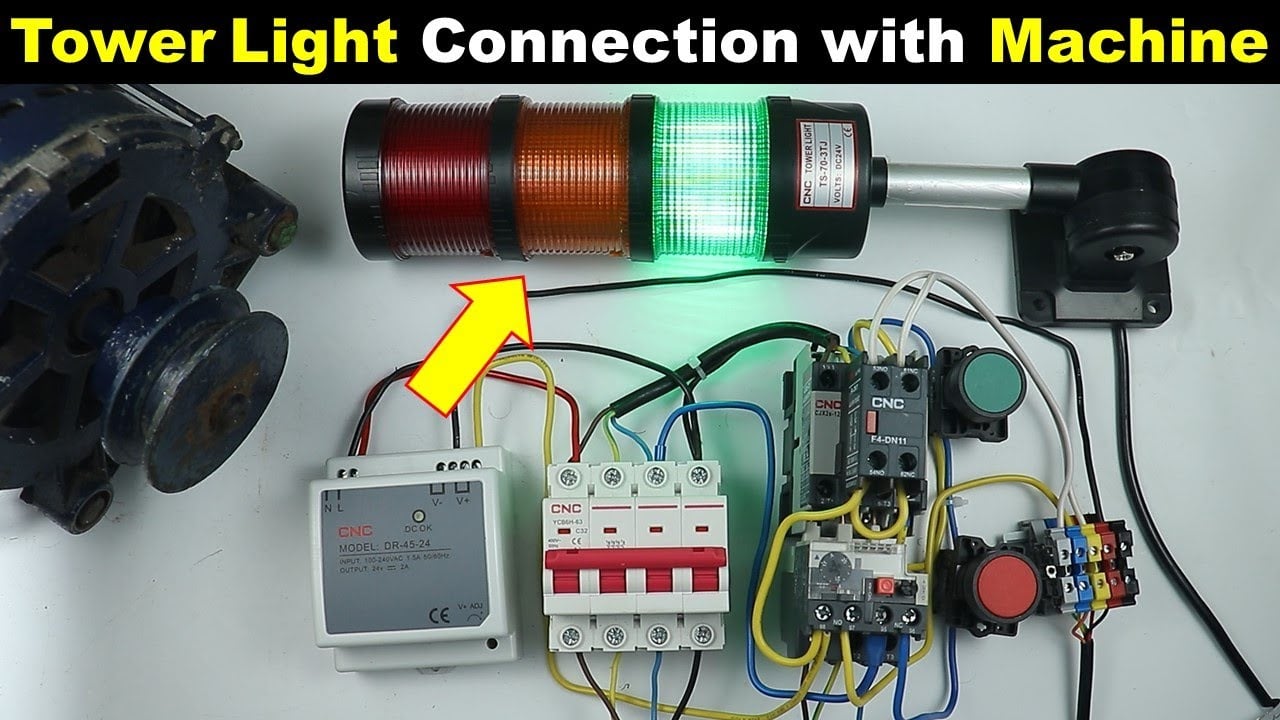
Watch the generic signal-tower wiring lesson.
Frequently asked questions
Is every tower-light common wire positive or negative?
No. The word “common” identifies a shared connection in a particular circuit diagram. Its polarity or role depends on the exact light and controller output. Check both wiring diagrams rather than relying on a generic color convention.
What is the difference between a sourcing and a sinking output?
A sourcing output provides the switched positive potential to a compatible load. A sinking output provides a switched return path. The output module’s manual identifies its topology, limits, and required common connections.
Can I use an HBJD-40 wiring diagram for an HBJD-40A tower?
Do not assume so. The ONPOW wiring guide lists differences in the models and their common conductors. Match the full order code and diagram before wiring.
Do all tower-light colors have separate input wires?
Not necessarily. Some assemblies provide separate leads; others use a different circuit, mode, or communication interface. Confirm the model diagram and input method.
Can I connect the buzzer common to the light common?
Only if the exact model documentation expressly shows that connection. The HBJD-40A wiring drawing distinguishes common leads for certain light and sound modes and includes a warning about combining them.
References
- ONPOW HBJD-40 / HBJD-40A signal-tower wiring guide
- National Instruments: Industrial digital I/O signal connections
- IEC 60204-1: Safety of machinery — electrical equipment of machines
- IEC 61310-1: Requirements for visual, acoustic and tactile signals



