

A push button minimum switching load is the lower electrical duty for which a particular contact configuration has a documented suitability claim. It is different from the maximum current printed in a product description. When a button operates a PLC input, logic input or other low-energy signal, a high maximum rating does not by itself establish reliable operation. Ask for the exact contact option, minimum applicable load and the conditions behind that figure. If the manufacturer does not provide a suitable claim, treat compatibility as unverified and arrange application qualification rather than inventing a universal minimum current.
Why a small signal needs its own compatibility check
Many industrial control panels use a mechanical button to send a command to an electronic input. The contact may carry much less current than a power-switching application. The job still requires a dependable change of input state across the intended operating conditions and service period. Merely observing one successful press at commissioning does not establish that performance.
The contact interface is affected by construction, material, surface condition, environment and the electrical circuit. Films or contamination can matter differently at different signal levels. A contact suitable for one switching duty is not automatically qualified for every smaller duty. Smaller current can reduce some electrical stresses, but it does not eliminate the need to check reliable signal transmission.
This is a selection and qualification question. Use the panduan pemandu kontak tombol tekan for the wider assembly and contact-function context. The contact resistance measurement guide addresses how a resistance test is defined and interpreted. The gold versus silver contact guide addresses material choices. Here the focus is whether the complete button-to-input combination has an adequate low-load basis for approval.
Distinguish four different ratings
A maximum switching rating describes an upper boundary under stated conditions. It may depend on supply type, load category, operating frequency and life expectations. A thermal current or insulation voltage is another characteristic and must not be silently treated as a switching-duty promise. Read the manufacturer’s definitions rather than choosing the largest number in a catalogue.
Minimum applicable load concerns the opposite end of the operating range. Its value, when provided, belongs to a particular contact construction and specified test or reliability conditions. It should not be transferred between families or between optional contact materials within a family. Do not convert a current-only statement into a voltage-current pair without supporting documentation.
Contact resistance is a measured electrical property under specified test conditions. A low initial reading can be useful, but it is not equivalent to a minimum-load suitability statement or a service-life guarantee. Likewise, mechanical life counts a different aspect of operation from electrical performance at the intended signal duty. Keep these fields separate in the purchasing comparison.
Describe the receiving input before choosing the switch
Identify the exact controller or interface input module, its wiring arrangement and the manufacturer’s electrical characteristics. Record the supply range, input current behavior and the thresholds used to recognize each state. A nominal system voltage alone is not enough to describe the contact duty. Include any diagnostic pulses, external interface components and documented input filtering that affect the circuit.
Establish whether the signal is a normal operational command or part of a safety-related function. A general low-load selection exercise cannot approve a safety circuit. Safety functions require the appropriate architecture, component suitability and validation under the applicable requirements. Do not add a resistor or substitute an interface relay to cure a signal problem without assessing its effect on the whole function.
Keep the mechanical contact and electronic input specifications together in the design record. A general interface example cannot establish an ONPOW product rating. Obtain documentation for the actual button and receiving input, and compare the complete circuit rather than copying component values from another application.
Request the correct contact option
Give the supplier the complete duty description rather than asking only for a button with a large current rating. Ask which contact option is intended for the specified signal circuit and what minimum-load information applies. If a plated contact is proposed, request the actual option identification and any restrictions on changing between power duty and signal duty.
Do not assume that a gold-colored terminal indicates gold contact surfaces. The externally visible terminal material and the internal contact interface are different things. A photograph cannot verify plating thickness, contact alloy or reliability at a particular input current. Similarly, a marketing phrase such as low resistance does not replace a specified test method and acceptance criterion.
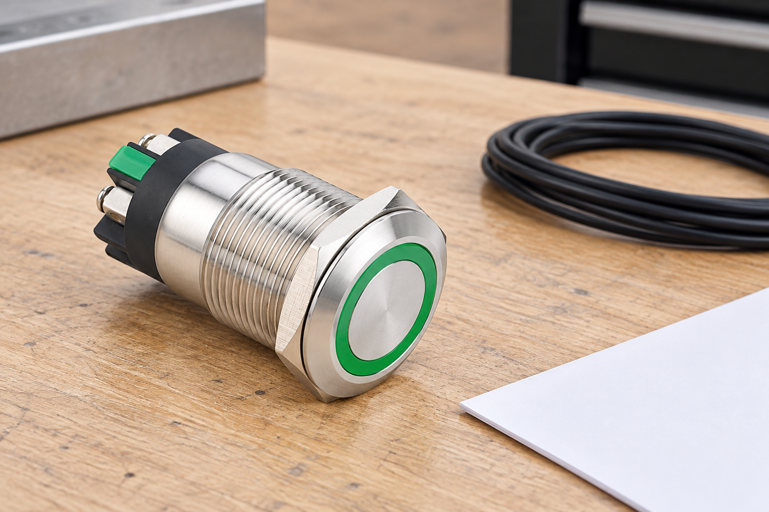
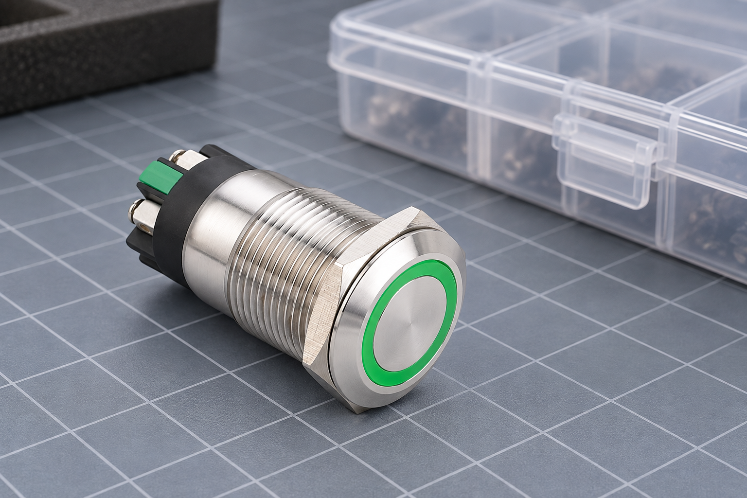
The LAS1GQ-11E/L/S page illustrates a real industrial button construction. Its published general specifications must not be expanded into an undocumented minimum switching load. Ask ONPOW for written confirmation of the ordered contact option and the proposed input duty before selecting it for a sensitive low-energy application.
Build an evidence-based selection table
Use the following comparison as a purchasing record. The entries describe evidence to obtain, not numerical limits for an unspecified model. A blank or unavailable field is an open engineering question, rather than an invitation to copy a value from a competing manufacturer’s relay or switch.
| Decision field | Evidence required | Common mistake to avoid |
|---|---|---|
| Button identity | Complete part code and contact option | Approving a family photograph instead of a configuration |
| Input duty | Actual input documentation and circuit description | Using nominal voltage as the entire load description |
| Minimum applicable load | Manufacturer statement with conditions | Inferring the minimum from the maximum rating |
| Contact material | Documented internal contact specification | Judging material from terminal color |
| Metode verifikasi | Approved test circuit and acceptance criteria | Treating a continuity beep as a reliability study |
| Service conditions | Environment, duty and maintenance assumptions | Extrapolating a clean bench trial to every installation |
If two candidates have different documentation quality, reflect that uncertainty in the approval record. A candidate with a complete low-load statement may require less application testing than one without it, but the receiving input and environment still need to match the stated conditions. Price and head appearance cannot resolve a missing electrical suitability claim.
Plan an application test that can answer the question
Define the operating conditions, sample identity, circuit and acceptance criteria before testing. Specify how a missed command, excessive resistance, intermittent signal or unintended state transition will be detected. Include the receiving input and its actual wiring where practical, because a meter connected alone may not reproduce the application duty.
A useful test distinguishes contact behavior from software filtering and wiring errors. Record both the physical operation and the input response with suitable equipment. A controller’s filter may suppress short events, but it does not create a material suitability claim for the contact. Changing the filter during the test can hide an intermittent response unless the change is documented and assessed.
The ASTM B539 standard page identifies a formal framework for measuring resistance of electrical connections. It does not supply universal acceptance limits for an ONPOW push button. Use an approved, applicable method and manufacturer-defined limits; do not claim compliance with a complete standard from reading its public catalogue description.
Avoid damaging the evidence during investigation
Repeated power switching or an unapproved high-energy resistance test can change the contact condition being investigated. For a low-signal complaint, discuss the proposed test sequence with the supplier before applying a different electrical duty. Keep samples identified and document their prior service. A unit that has already switched a different load is not necessarily representative of a new signal-duty unit.
Do not scrape internal surfaces or open a sealed switch to make it pass. Such action changes the specimen and may compromise the construction. If teardown is authorized for failure analysis, record it separately from the qualification result. Preserve an untouched sample when possible so the supplier can evaluate the original symptom.
All panel work requires the proper isolation and competence. The HSE electrical maintenance guidance provides general safety principles for this work. Even a nominally low-voltage input may be located beside hazardous circuits or be connected to external equipment. Plan the investigation for the actual installation, not the label assigned to one signal wire.
Decide whether an interface is justified
If the mechanical contact cannot be qualified for the input duty, an approved interface may be an engineering option. It is not automatically an improvement: an extra relay or electronic module introduces its own input requirements, response characteristics, failure modes and maintenance needs. Its output must also suit the receiving input.
Compare a directly compatible contact option with an interface-based solution at system level. Include space, supply availability, diagnostics, replaceability and the consequence of failure. For safety-related circuits, involve the responsible safety engineer. An added interface must not defeat monitoring or change the required behavior without documented validation.
Approve the final arrangement only after the exact components, circuit and acceptance evidence are recorded. Update the bill of materials and drawings so maintenance staff do not later substitute an outwardly identical contact option. Retain the supplier’s minimum-load statement and test record with the approved configuration. This prevents a one-time engineering decision from being lost during routine purchasing.
Pertanyaan yang sering diajukan
Does a higher maximum current rating mean better PLC-input performance?
No. Maximum switching capability and low-load suitability answer different questions. Obtain the minimum applicable load information for the exact contact option and compare it with the receiving input and service conditions.
Is there a universal minimum current for all push buttons?
No universal value should be assumed. The applicable lower duty depends on the contact construction and the manufacturer’s stated conditions. Missing data must remain unverified until appropriate confirmation or qualification is obtained.
Does a continuity beep prove the input circuit will remain reliable?
No. A beep indicates the meter’s response under its own test conditions at that moment. It does not establish long-term low-load performance, the input’s state thresholds or behavior across the intended environment and operating duty.
Can a resistor solve a low-load compatibility problem?
A circuit change may be considered by the responsible engineer, but an arbitrary resistor is not an approved remedy. Evaluate current, heat, diagnostics and failure behavior, then document and validate the complete arrangement before use.
Further learning
University electrical measurement background. This does not establish an ONPOW minimum load or a contact reliability limit.
NPTEL: Electrical Measurement and Electronic Instruments — NPTEL IIT Kharagpur



