

A flyback diode across a DC relay coil gives the coil current a path after the driver turns off, limiting the turn-off voltage seen by the control circuit. In the usual arrangement, the diode is reverse-biased while the coil is powered and conducts during the turn-off transient. That principle does not specify a diode part number, authorize a polarity guess, or protect the relay’s load contacts automatically. Select suppression from the exact coil, driver, and machine requirements, including release time. This guide covers DC coil suppression; a simple flyback diode must not be treated as a universal solution for an AC coil.
What changes when a DC coil is switched off
A relay coil stores energy in its magnetic field while current flows. When the control circuit interrupts that current, the coil produces a voltage that opposes the rapid change. Without an appropriate path or clamp, the driver and surrounding circuit can experience a turn-off transient beyond what the designer intended.
A flyback diode provides a recirculating current path around the coil after turn-off. That reduces the voltage excursion but also changes how the stored energy decays. The relay does not necessarily release at the instant the controller removes its command. The coil’s electrical behavior and the relay’s mechanical release behavior must both be considered.
cURL Too many subrequests by single Worker invocation. To configure this limit, refer to https://developers.cloudflare.com/workers/wrangler/configuration/#limits’ inductive-load turn-off application brief distinguishes a clamp at the switch, a clamp at the load, and a freewheeling path. Its examples concern semiconductor power switches. They help explain energy management, but they do not provide an approved suppression part or a release-time specification for an ONPOW relay.
Separate the coil driver from the load contacts
The coil circuit operates the relay mechanism. The load-contact circuit switches another electrical path. A diode placed across the coil affects that coil’s turn-off transient; it does not automatically manage the inductive energy of a motor, solenoid, or other load switched by the contacts.
For example, a controller output may drive a DC relay coil while the relay contacts switch an AC load. The coil can require DC suppression and the load can require a different contact-side review. The use of one diode on the coil is not evidence that the AC contact circuit is protected or that the load rating is suitable.
Użyj Przewodnik po schematach okablowania przekaźników elektromechanicznych to identify these two paths. For the separate load-contact problem, see relay contact arcing and suppression. Keeping the topics separate avoids assigning the right component to the wrong part of the circuit.
Read the exact polarity and suppression diagram
A conventional diode across a DC coil is oriented so it does not conduct during normal energization. Its cathode is on the positive side in that conventional circuit, and its anode is on the negative side. This is a description of that circuit topology, not a terminal instruction for an unidentified relay, socket, or driver.
Check whether the coil or socket already contains a diode, indicator, resistor, rectifier, or another suppression element. Built-in components can create polarity requirements that a bare coil would not have. A replacement with the same socket outline may differ electrically. Follow the exact internal schematic and current manufacturer instructions.
Do not infer polarity from wire color, the location of the coil pins, or a picture of a different relay. Confirm the terminal-view direction and the order code. Applying supply to an incorrectly oriented diode can create an unintended current path and damage the driver or protection components. Circuit review must resolve that uncertainty before power is applied.
Compare suppression approaches by their effect
The following table is a review aid for a qualified circuit designer. It provides no component values or approved wiring for a particular relay. Suitability depends on the coil energy, driver limits, release requirements, and equipment documentation.
| Approach | Main purpose to evaluate | Important trade-off | Potrzebne informacje |
|---|---|---|---|
| Simple diode across a DC coil | Provide a recirculating path at turn-off | Coil current can decay slowly enough to affect release time | Coil data, driver limits, polarity, required release behavior |
| Higher-voltage clamp arrangement | Limit the transient at an engineered clamp level | Higher voltage can change energy dissipation and driver stress | Maximum transient rating, clamp tolerance, pulse energy, timing |
| Manufacturer-integrated suppression | Use the circuit specified for the exact assembly | Polarity or release behavior may differ from a bare coil | Internal diagram, approved supply, replacement compatibility |
| No added external suppression | Rely on an already validated driver or assembly arrangement | Must be supported by documentation and testing, not convenience | cURL Too many subrequests by single Worker invocation. To configure this limit, refer to https://developers.cloudflare.com/workers/wrangler/configuration/#limits |
cURL Too many subrequests by single Worker invocation. To configure this limit, refer to https://developers.cloudflare.com/workers/wrangler/configuration/#limits.
Specify current, voltage, energy, and repetition together
cURL Too many subrequests by single Worker invocation. To configure this limit, refer to https://developers.cloudflare.com/workers/wrangler/configuration/#limits.
cURL Too many subrequests by single Worker invocation. To configure this limit, refer to https://developers.cloudflare.com/workers/wrangler/configuration/#limits.
cURL Too many subrequests by single Worker invocation. To configure this limit, refer to https://developers.cloudflare.com/workers/wrangler/configuration/#limits.
Release time is part of the application requirement
cURL Too many subrequests by single Worker invocation. To configure this limit, refer to https://developers.cloudflare.com/workers/wrangler/configuration/#limits.
cURL Too many subrequests by single Worker invocation. To configure this limit, refer to https://developers.cloudflare.com/workers/wrangler/configuration/#limits.
cURL Too many subrequests by single Worker invocation. To configure this limit, refer to https://developers.cloudflare.com/workers/wrangler/configuration/#limits.
Confirm the ONPOW model and its stated ratings
Ten cURL Too many subrequests by single Worker invocation. To configure this limit, refer to https://developers.cloudflare.com/workers/wrangler/configuration/#limits lists model-specific resistive contact ratings and separate coil-related characteristics. Those contact ratings do not select a flyback diode. Obtain the exact coil supply code, internal circuit, driver interface, and suppression or socket details for the unit being ordered.
The product page lists an operating-time value, but an operating time is not the same as a release time under a particular suppression arrangement. Do not convert that published figure into a promised turn-off performance. Ask for the release behavior and applicable measurement conditions if timing matters to the application.
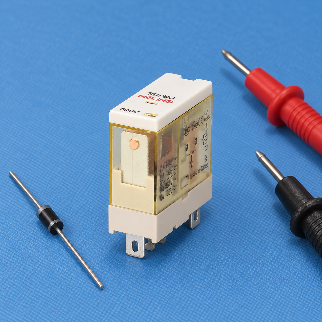
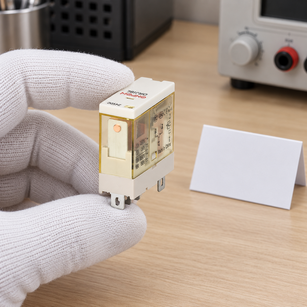
The relay photographed here is shown disconnected. The separate diode is an illustrative component, not a selected part number and not a wiring instruction. Neither the picture nor a visible coil-voltage marking proves that every relay sold under the same family name uses that voltage or suppression configuration.
For standards context, IEC 61810-1 addresses electromechanical elementary relays. It does not approve a specific suppression circuit by association. Use current product documentation and the standards applicable to the complete equipment.
Check an existing circuit before adding another diode
Start with the approved schematic and complete order codes. Identify the controller output, coil supply, coil terminals, socket accessories, indicators, and any clamp already present. A second suppression component can change the existing circuit rather than simply improve it. Confirm that the supplier permits the proposed arrangement.
Inspect and measure only under the required safe-work procedure. 29 CFR 1910.333 provides United States electrical-work context, including de-energizing and verification. A relay coil command being Off is not, on its own, proof that the equipment is de-energized.
When commissioning is authorized, record the driver command, relay release, and relevant machine response using suitable methods. A handheld meter may show steady voltage while missing a short transient. The test plan must suit the signals being evaluated and the personnel’s qualifications. Do not probe energized equipment merely to confirm an internet circuit example.
Include suppression in the replacement and purchasing record
Request the exact coil code, nominal supply type, permitted operating range, coil demand, internal suppression, polarity, socket compatibility, driver requirements, and release-time conditions. Include the intended switching duty and relevant environmental constraints. This information is more useful than a general request for a protected relay.
For a later replacement, retain both the relay and suppression-module identities. Record any approved clamp changes with the schematic revision and verified timing results. The przewodnik wyboru przekaźników covers the broader specification. For model-specific information, skontaktuj się z ONPOW with the actual coil and driver application.
Film edukacyjny
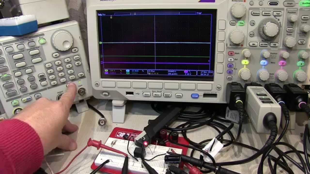
#183: Why diodes are used around relay coils: Back to Basics on flyback or snubber diodes by w2aew. This tutorial explains DC inductive turn-off. It does not approve an AC coil suppressor, a specific diode, or an ONPOW circuit. Otwórz film na YouTube.
Często zadawane pytania
Does a flyback diode protect the relay’s switched load contacts?
Nie automatycznie. Dioda cewki obsługuje obwód cewki. Obciążenie indukcyjne przełączane przez styki wymaga osobnej analizy zastosowania.
Czy mogę użyć zwykłej diody gaszącej przepięcia (flyback) w przypadku cewki zasilanej prądem przemiennym (AC)?
Nie traktuj tego jako uniwersalnego rozwiązania AC. Potwierdź dokładną cewkę AC, sterownik i zatwierdzony przez producenta układ tłumienia.
Why can a diode change relay release time?
Ścieżka recyrkulacji pozwala na utrzymanie prądu cewki i jej pola magnetycznego po zakończeniu polecenia sterującego. Dokładny czas zależy od pełnego obwodu i przekaźnika.
Can I choose the diode from the relay’s contact-current rating?
Nie. Dopuszczalne prądy kontaktu opisują inną ścieżkę elektryczną. Wybór diody wymaga informacji o cewce i układzie sterującym, zachowaniu transientnym oraz warunkach pracy.
What if the socket already has a suppression module?
Przeczytaj jego wewnętrzny schemat i dokumentację przed dodaniem lub wymianą czegokolwiek. Wbudowane tłumienie może narzucać wymagania dotyczące polaryzacji i czasu.



