

Electromechanical relay failure modes include a coil that cannot produce the required motion, contacts that fail to close or open correctly, a mechanism that sticks or wears, and external socket or wiring faults that mimic a failed relay. Diagnose the observed failure before replacing the part. A click does not prove that the load contact is healthy, and an indicator on the relay does not prove that the intended load has power. Record the coil conditions, contact load, switching history, environment, and physical evidence. Repeated replacement without identifying the cause can repeat the same failure.
Classify the observed symptom before naming the cause
Begin with what the equipment actually does: no pickup, intermittent operation, chatter, failure to release, load not energized, or load remaining energized. Record whether the symptom is continuous, temperature-related, linked to another load starting, or associated with a particular machine step.
Separate the command, coil supply, mechanical movement, contact state, socket connection, and load response. A controller can command a relay while a wiring fault prevents the coil from receiving the intended supply. Conversely, the relay can move while a load conductor or socket connection remains open.
O electromechanical relay selection guide covers specification. The relay testing guide addresses a controlled verification process. This article focuses on classifying failures and preserving evidence for corrective action.
Coil-side failures and supply problems
A damaged coil, wrong supply variant, unsuitable voltage conditions, or an external connection fault can prevent the armature from moving correctly. Compare the actual model’s AC/DC and voltage requirements with the circuit documentation. Similar-looking relays can have different coil versions.
Chatter may reflect an unstable supply, a control signal that repeatedly changes, a poor connection, or mechanical behavior. It is an observation, not proof of one cause. Repeated movement can also stress the contacts and make a supply problem appear later as a contact failure.
A coil indicator can show only the condition represented by its circuit. It may not prove correct pickup, contact closure, or load power. Keep indicator behavior separate from the required measurement and contact-state evidence.
| Observed symptom | Failure categories to investigate | Evidence that helps separate them |
|---|---|---|
| No pickup | Supply, coil, connection, mechanical obstruction | Exact coil variant, circuit condition, approved movement checks |
| Chatter | Unstable command or supply, connection, mechanism | Timing correlation and controlled circuit observations |
| Click but no load response | Contact, socket, conductor, load | Contact path and load-circuit evidence |
| Failure to release | Continued coil drive, suppression effects, mechanical sticking, welded contacts | Coil state, release behavior, isolated contact condition |
| Intermittent load | Contact wear, loose socket, wiring, unstable drive | Repeatable fault conditions and physical inspection |
| Repeated early failure | Application mismatch or unresolved environment | Load category, inrush, frequency, temperature, mounting |
The table is a diagnostic framework, not permission for improvised energized measurements or bypassing controls.
Contact failures can have opposite visible outcomes
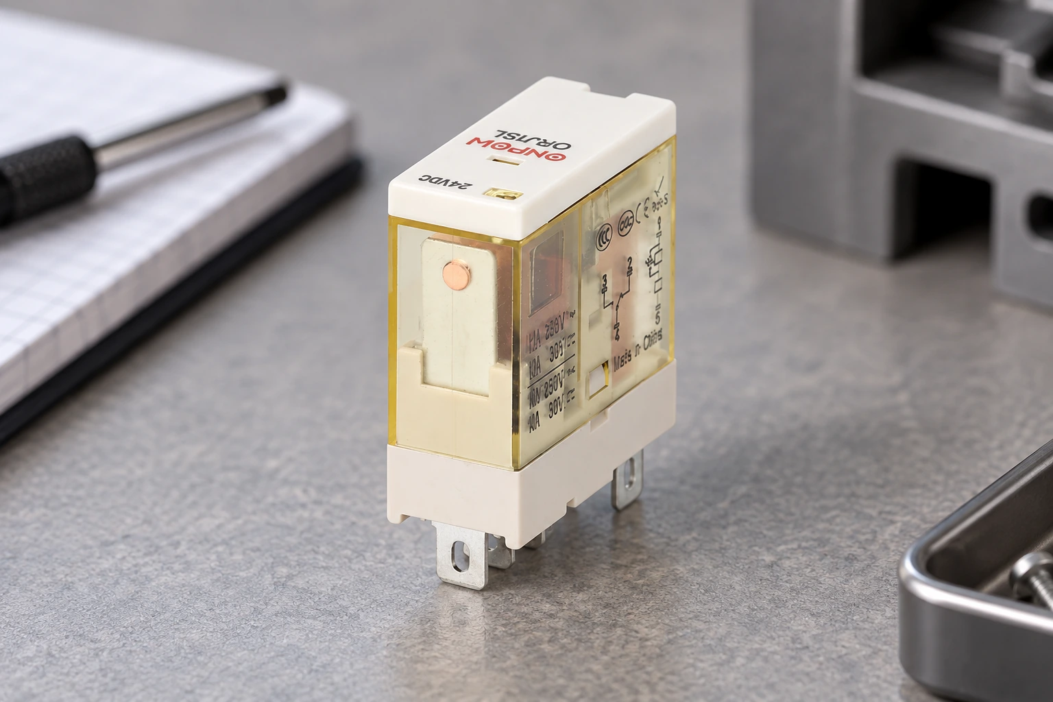
A contact can fail to make a reliable connection because of wear, erosion, contamination, insufficient suitability for the actual signal, or another condition. It can also remain closed when it should open, including through welding or a mechanical failure. These outcomes require different evidence.
O TI relay-technology application note discusses arcing and possible contact welding in electromechanical relays. It is a general explanation, not an ONPOW failure-rate claim. The actual load and switching conditions must be reviewed for the selected relay.
Do not use an unloaded continuity result as proof that a contact performs correctly under its intended load. Equally, a low-level test can need interpretation against the contact’s minimum switching conditions. Use the relay manufacturer’s data and the approved test method rather than treating every meter reading as conclusive.
Compare the load with the actual contact rating
A resistive rating does not automatically apply to a motor, lamp, coil, capacitive input, or another load with inrush or turn-off behavior. Record nominal current, relevant starting or transient current, supply type, switching frequency, and the manufacturer’s applicable load category.
A contact can have adequate thermal capacity while its switching duty remains unsuitable. Keep current carrying and making/breaking requirements distinct. If the machine switches more frequently than the original design assumed, evaluate the resulting duty rather than selecting a replacement only by ampere number.
O relay contact-arcing guide discusses one related application issue. Use its principles with model-specific ratings and a reviewed circuit; do not add a suppression component without considering the load, output device, and response requirements.
Failure to release is not always a welded contact
A relay may remain energized because the controller continues driving its coil, a wiring fault supplies it, or the circuit behaves differently from the expected drawing. Some suppression arrangements can also influence release time. Mechanical sticking and welded contacts are other categories.
Identify whether the coil has reached its specified release condition and whether the armature and contact paths respond as required. The actual diagnostic procedure must be performed by qualified personnel using appropriate isolation and instruments. Do not repeatedly tap the case or bypass the circuit as a substitute for finding the cause.
For a DC-coil suppression context, read flyback diodes for relay coils. That separate topic should not be transferred to an AC coil or interpreted as a universal diode specification.
Mechanical and environmental evidence matters
Dust, contamination, vibration, mounting, heat, and physical damage can affect the assembly or its connections. A socket that is loose or overheated can mimic an internal relay problem. Inspect the complete installation, including retention and conductor support, before assigning blame to the removable relay.
Preserve physical evidence where a repeated or significant failure is being investigated. Photograph the label, case, socket, terminals, and visible damage before disturbing them. Keep the failed part identified with its machine location and fault history. Do not open or modify it if that would prevent the supplier’s agreed failure analysis.
Unusual mechanisms also exist. A NASA-hosted relay failure investigation documents an unexpected conductive path in particular relays. It illustrates why physical evidence can matter; it does not show that this is common in ONPOW products or that every intermittent contact has that cause.
Separate socket and wiring faults from the relay itself
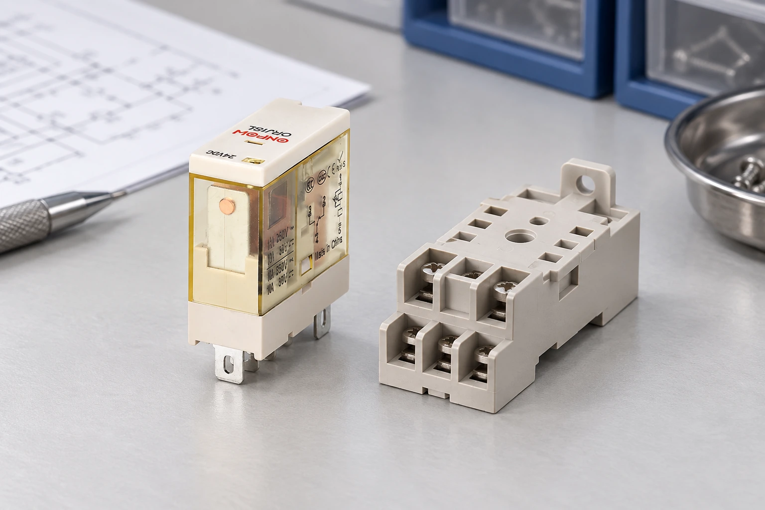
Check the exact relay/socket compatibility and terminal map. A part that enters a socket can still have an inappropriate contact arrangement or coil connection. Retention, contact condition, and conductor termination must meet the relevant installation instructions.
A loose or damaged socket connection can create heating, intermittent operation, or voltage loss. Replacing only the relay may temporarily alter the connection and hide the symptom without correcting it. Include the socket and associated wiring in the approved diagnostic record.
For the physical reference, this article uses an ONPOW ORJ1SL relay example. Its photograph does not establish suitability for every socket, coil supply, load, or protective function discussed. Request the exact variant’s current data and connection drawing before specifying a replacement.
Investigate repeat failures as an application problem
Build a simple history with installation date, failure observation, part code, operating duty, load, ambient conditions, and changes to the machine. Compare failures by circuit location and condition. A cluster after a program change or a new load is more informative than a general statement that relays do not last.
Review whether the selected relay meets the actual electrical and environmental requirements. Examine coil supply stability, load switching, suppression, socket condition, and operating frequency. If the application has changed, the original selection needs review even when every replacement part is genuine.
Do not turn a catalogue mechanical-life figure into a guaranteed maintenance interval. Electrical and application conditions affect the result. A preventive replacement strategy should be based on the equipment’s requirements, actual duty, evidence, and the responsible engineering decision.
Keep diagnostic work inside the authorized procedure
Installed equipment can contain hazardous voltage and stored energy. Qualified personnel must follow the applicable isolation and work procedures. In United States workplaces, relevant requirements include 29 CFR 1910.147 e 29 CFR 1910.333.
Do not assume that removing coil power isolates every contact circuit. A relay can switch another supply or several separately supplied circuits. Identify the complete circuit before handling the component, socket, or connected conductors. A relay LED and an HMI state do not prove absence of electrical energy.
Any energized diagnostic step must be justified and performed under the approved procedure. The aim is to obtain evidence with the required controls, not to improvise a shortcut because the relay is small or easy to unplug.
Supplier failure-analysis enquiry
Send the full relay and socket codes, coil supply, switched-load details, circuit drawing, operating frequency, environment, symptoms, and photographs. Explain which observations were confirmed and which remain suspected. Include changes to the load or control sequence and preserve the failed component as agreed with the supplier.
Ask whether the exact variant supports the duty and what additional evidence is needed. A good corrective action can involve a different suitable part, circuit interface, mounting, socket, suppression design, or maintenance control. Record the actual cause when established and verify the affected function after the change.
Vídeo educativo
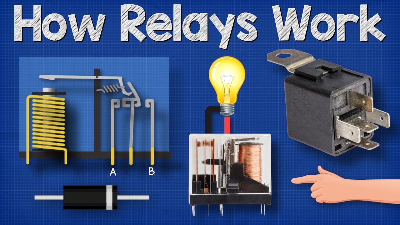
How Relays Work – Basic working principle electronics engineering electrician amp by The Engineering Mindset. General educational background. Use the selected product drawing and the machine design for the actual circuit and installation. Watch on YouTube.
Perguntas frequentes
Does a relay click prove its contacts are good?
No. A click indicates some mechanical movement. The required contact path and load response need their own verification.
Is every relay that will not release contact-welded?
No. Continued coil drive, wiring faults, suppression-related timing, and mechanical sticking are other possibilities. Confirm the evidence before assigning the cause.
Can a bad socket look like a failed relay?
Yes. Poor connections or incompatible terminals can affect coil or load paths. Include the socket and wiring in the approved inspection.
Does the printed resistive rating cover every load?
No. Motors, coils, lamps, and other loads can have different switching demands. Use the applicable rating for the actual circuit.
What should be preserved for a supplier investigation?
Keep the failed part identified, its codes and location, fault history, circuit and load data, conditions, and photographs of the undisturbed installation and damage.



