Push button mounting depth must include the rear component assembly, the required wire exit, connection tools and service movement. The distance from the panel to the end of an unconnected switch is only part of the required space. Check the actual product configuration in the closed enclosure and throughout the door’s intended movement. A switch that fits a panel hole can still interfere with cable ducts, terminals or adjacent equipment. This guide explains how to build a rear-clearance check without inventing a universal depth allowance or bend radius.
Start with the configured assembly drawing
Obtain the drawing for the exact ordered switch, including the operator, holder, contact blocks, lamp module and accessories where applicable. A family-level drawing can omit options that change the rear envelope. Record the drawing revision and confirm which dimensions refer to the front face, panel mounting plane and rear components.
Keep the panel stack in the same record. Material thickness, coatings, seals and permitted legend accessories can affect the installed relationship. Use the manufacturer’s approved arrangement rather than adding washers or spacers to make a preferred layout fit. A dimensional review should represent the final assembly, not a convenient simplified version.
The panel-mounted push button selection guide addresses the wider physical interface. Here the focus is the space behind that interface: everything needed to connect, inspect, operate and maintain the actual device after installation.
Establish a common reference plane
Use the panel mounting plane as the shared reference for component and enclosure drawings. Make sure dimensions are not being compared from different surfaces. A front projection, total product length and rear depth can describe different distances; confusing them can make an apparently adequate enclosure too shallow.
Identify the actual internal obstruction, not just the enclosure’s advertised depth. A backplate, cable duct, door hardware or neighboring device may be closer to the switch than the enclosure wall. Include items attached to both the door and the fixed structure, because their relative positions change during opening.
For modified equipment, inspect the installed condition and reconcile it with the drawing. Document any added components or changes to wire routing. Do not approve a replacement based only on an old layout when later maintenance has filled the available space.
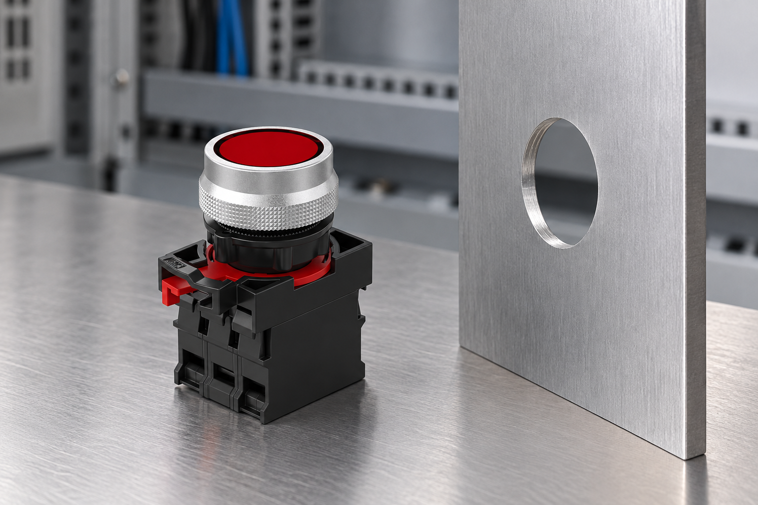
Separate component, wiring and service envelopes
Treat rear clearance as several related envelopes. The component envelope covers the configured hardware. The connection envelope includes the actual prepared conductors or connectors. The service envelope includes the tool and movement needed for approved assembly, inspection and replacement.
These spaces can overlap in a planned design, but they should not be ignored. A wire may physically fit between the switch and a cable duct while leaving no way to inspect or release its connection. A removable rear block may require a direction of movement that a neighboring device prevents.
| Envelope | Include | Verify with |
|---|---|---|
| Configured hardware | Holder, blocks, lamp and accessories | Exact assembly drawing |
| Connected wiring | Terminal preparation, connector and wire exit | Approved connection information |
| Wire routing | Support points, movement and bend requirements | Cable and equipment instructions |
| Assembly access | Tool approach and inspection view | Production or service procedure |
| Replacement access | Permitted removal direction and service length | Manufacturer’s replacement instructions |
| Door movement | Relative motion and possible obstructions | Installed layout or representative mock-up |
The table defines review categories rather than fixed allowances. Do not add an arbitrary distance to every switch and present it as a manufacturer requirement.
Use the actual terminal and conductor arrangement
Connection style changes how space is used. A screw terminal needs the approved tool access and conductor route. A plug or connector adds its own body and removal space. A soldered or prewired assembly still needs support and the service arrangement defined by the equipment design.
Obtain the relevant wire and cable information. The required bend behavior depends on the actual construction and application, so do not assign a universal radius from the switch diameter. Include any insulation sleeve, ferrule collar or connector housing that changes the prepared end’s envelope.
Review conductor identification as well as fit. Labels must remain usable after the wires are routed. A crowded layout that hides identifiers or prevents the correct conductor being disconnected is a maintenance problem even if the enclosure can be closed.
Check the whole door sweep
An assembly mounted on a hinged door moves relative to the backplate and nearby equipment. Inspect its clearance through the intended opening range, including the closed position and any specified service position. A check made only with the door fully open can miss the most restrictive point.
Observe the wiring path during that movement under a safe inspection procedure. Conductors should not become taut, be trapped at a hinge or press against the rear switch assembly. The wire support arrangement should control movement without transferring the bundle’s load to the terminals.
Include door stops, restraints and grounding arrangements in the equipment-level review. Do not remove an intended restraint to gain a little more opening space without an approved design change. The switch clearance decision must remain consistent with the finished enclosure’s safe service arrangement.
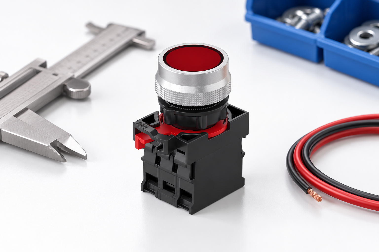
Avoid using the switch as a mechanical stop
The rear assembly should not bear against a cable duct lid, backplate or other component when the door closes. Contact may apply force to the operator, holder, blocks or terminals even when it does not visibly prevent closure. Investigate evidence of rubbing, displaced wiring or a change in button movement with door position.
Do not solve interference by bending terminals, trimming a holder, removing a required accessory or forcing wires into a smaller space. These actions can create an unapproved configuration. Review the layout, select an appropriate documented configuration or change the enclosure design through the proper process.
The ONPOW26-11 product provides a real rear-assembly reference. Its photograph illustrates the shape that a clearance review must account for; it does not supply a universal mounting depth or authorize changing its rear components. Obtain the exact drawing for the ordered version.
Build a representative layout check
Use the configured product and intended wiring arrangement in a representative fixture or the planned enclosure where appropriate. A mock-up is most useful when it includes the actual panel stack, nearby obstructions, cable support and service tools. A loose switch held in an empty cabinet does not test these interfaces.
Define what the check must demonstrate: no unintended mechanical interference, a permitted wire route, adequate tool access and an achievable replacement sequence. Record the configuration and photographs so that the result can be reviewed later. Keep any unresolved assumptions visible.
If a digital model is used, confirm that simplified component shapes have not omitted latches, screws or connector release features. Use the appropriate drawing revision and the actual configured assembly. A model that represents only the main body can incorrectly show service access where none exists.
Review replacement and future maintenance
Determine whether a technician can remove the intended component without dismantling unrelated circuits. Some layouts may legitimately require additional steps, but those steps should be planned and documented. Service time and the risk of disturbing nearby connections belong in the design decision.
Provide the wire service length required by the approved repair method. Too little can prevent replacement; uncontrolled excess can interfere with other devices. The appropriate arrangement must come from the equipment design rather than a generic instruction to leave “extra wire.”
Utilize contact block guide when rear component selection affects the envelope. Review incoming inspection to ensure delivered components match the drawing used for the clearance decision. A dimensionally different substitute should trigger a new check.
Include clearance evidence in an RFQ
Provide the required switch function, exact panel stack, available rear space and relevant obstruction drawings. State the terminal method and conductor route, and describe the required service access. Ask the supplier for the configured rear dimensions and accessory information rather than only the nominal mounting diameter.
Keep the approved drawing and layout check with the equipment record. If another contact block, connector or lamp option is proposed, compare its complete envelope before accepting it. Similar front appearance does not mean the rear assembly occupies the same space.
Contact ONPOW with the exact configuration and space constraints when selecting a switch for a crowded panel. A useful answer identifies a documented product arrangement and its limits; it should not depend on an installer compressing wires or modifying the device to make it fit.
Perguntas frequentes
Is product length the same as required enclosure depth?
No. Product dimensions may use different reference surfaces, and the installed connection, wire route, obstructions and service access also require space. Compare the configured drawing with the actual enclosure layout.
How much extra space should I leave for wires?
There is no universal allowance. Use the actual terminal or connector geometry, conductor requirements, cable support and approved service method to establish the connection and routing envelope.
Should clearance be checked with the door open or closed?
Check the relevant opening range, including the closed position and intended service positions. Door-mounted components and wiring move relative to the fixed enclosure structure.
Can I bend a terminal to make a replacement fit?
Do not modify the device outside its approved instructions. Review the layout or choose an appropriate documented configuration through the equipment’s change process.
References and scope
HSE equipment maintenance guidance supports planning for safe maintenance, and HSE electrical maintenance safety provides the safe-work context. Actual product dimensions, wire requirements and removal procedures must come from the exact component and equipment documentation.
Further learning
University background on inspection and quality planning, using casting examples. Apply the planning principle to the dimensional and service-access checklist; the lecture does not provide switch mounting dimensions.