

An industrial limit switch replacement must preserve the required contact behavior, actuator geometry, mounting reference, electrical ratings, and machine timing. Matching the body size or copying the wire colors is not enough. Before removing the old component, record its full part number, contact diagram, installed position, target motion, and control-system meaning. After fitting the approved replacement, verify both operation and release through the machine’s commissioning procedure. If the original device belongs to a protective function, retain that function’s specified capabilities and validation requirements. Do not treat an ordinary process switch as an interchangeable safety device.
Confirm the fault before selecting a replacement
A missing position signal can result from a damaged contact, loose conductor, shifted bracket, worn target, controller-input problem, or a changed program. Replacing the switch without identifying the cause can leave the failure in place. A switch that works by hand but not under the machine target suggests a mechanical-interface problem worth checking.
Record the observed condition and the expected state. Compare physical target position, actuator movement, contact state, input indication, and machine response using the approved diagnostic process. Each layer can disagree with the next, so a single HMI message does not establish that the field device has failed.
If the switch shows damage, investigate why. A bent actuator may indicate collision or side loading; burnt contacts may indicate an unsuitable load; a loose bracket can shift operation timing. Correct the installation cause as well as replacing the component.
Save the installation reference before disturbing it
Photograph the part label, actuator, bracket, target, conductor labels, and terminal area. Record mounting coordinates or the approved adjustment references from the machine documentation. Mark the distinction between a recorded reference and a new adjustment; the goal is not to recreate an uncertain position from memory.
Identify the contact drawing and wire numbers. Colors alone are not a reliable terminal map. A replacement with a similar body can have different terminal positions or numbering. Document the physical unoperated and operated conditions and what the receiving controller should report in each.
Земля limit-switch NO/NC wiring guide covers this electrical interpretation. The limit-switch actuator types guide addresses matching the target’s mechanical motion.
Compare replacement candidates field by field
Use the exact suffix and current product documentation. A series name can include several actuators, contact arrangements, terminal forms, seals, and ratings. A catalogue photograph may illustrate one version while the ordered suffix describes another.
| Required match | What to compare | Risk of an unchecked difference |
|---|---|---|
| Функция связи | Circuit, normal state, transfer behavior | Reversed or unexpected signal |
| Terminal map | Numbering, position, connection method | Incorrect field wiring |
| Actuator | Type, contact point, direction, force | Missed operation or binding |
| Travel | Operating, release, permitted final position | Changed timing or excessive compression |
| Монтаж | Hole spacing, support, adjustment reference | Shifted detection position |
| Electrical data | AC/DC load, category, minimum load, life | Contact damage or unreliable input |
| Окружающая среда | Temperature, contamination, ingress protection | Early failure in service |
| Protective role | Specified capabilities and validation | Loss of required protective performance |
The comparison does not create a drop-in replacement approval. The equipment owner or responsible engineer must assess the actual differences and the resulting installation.
Contact-state equivalence comes before wire position
A conventional changeover contact may have COM, NC, and NO, but their physical locations are model-specific. Confirm which path is closed in the defined reference position and which closes after operation. Then map the existing circuit to the new drawing.
The machine’s normal position may hold the actuator operated. In that case, copying an assumption that NC means normal machine state can reverse the intended indication. Keep the mechanical reference and control meaning separate in the replacement record.
For an ordinary monitored circuit, review the response to open conductors, short circuits, stuck contacts, and failed reset. NC can make some signal losses visible but does not establish complete fault detection. For protective functions, use the approved device and circuit design rather than inferring suitability from contact names.
Preserve the operating position and the release position
Two actuators can change contacts at different positions despite fitting the same bracket. Compare the operating dimension relative to the mounting reference. Account for actuator length, cam contact point, roller diameter where relevant, and the direction of target approach.
Release is equally important. A replacement can operate at the expected point yet remain active longer during withdrawal. That can change a sequence, prevent the next cycle, or alter a recovery condition. Confirm the target moves far enough to cross the new release point over the relevant tolerances.
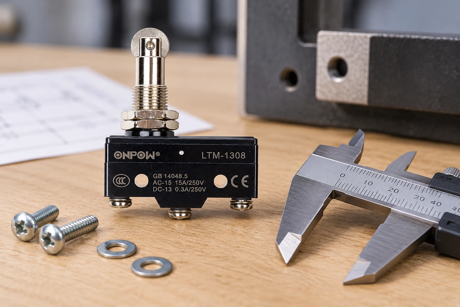
Земля roller-plunger limit-switch guide explains one common interface. A real ONPOW LTM-1308 example is shown in this article, but its photograph does not establish compatibility with an existing mechanism or provide universal travel dimensions.
Do not transfer a printed current rating between loads
Check the actual switched circuit. A resistive-load rating does not automatically cover a relay coil, solenoid, motor, lamp, or small electronic input. AC and DC switching behavior can also differ. Keep the applicable voltage, current, load category, switching frequency, and expected electrical life in the comparison.
If the previous switch failed electrically, inspect the circuit load and interface before installing an identical replacement. A repeated failure may reflect an unsuitable load or suppression arrangement rather than an isolated defective component. Review any replacement of a direct-switched load with a control interface as a circuit change requiring engineering approval.
Земля IEC 60947-5-1 publication information gives standards context for electromechanical control circuit devices. It is not a certificate for an individual part and does not make every device marked with a similar current number equivalent.
Control energy before removal and adjustment
Only qualified personnel should inspect or replace installed electrical and machine-control components. Use the machine’s applicable energy-control procedure, including stored mechanical, pneumatic, hydraulic, and electrical energy. A control stop or limit contact is not an energy-isolating device by itself.
For United States workplaces, relevant requirements include 29 CFR 1910.147 и 29 CFR 1910.333. Follow the rules and procedures applicable to the actual equipment and work, rather than treating a replacement article as a complete maintenance instruction.
Preserve the removed component and record its condition where useful for diagnosis. Avoid live adjustment around moving machinery. Any temporary restoration for testing must follow the equipment’s authorized process, with the required personnel and safeguards in place.
Inspect the bracket, target, and wiring during installation
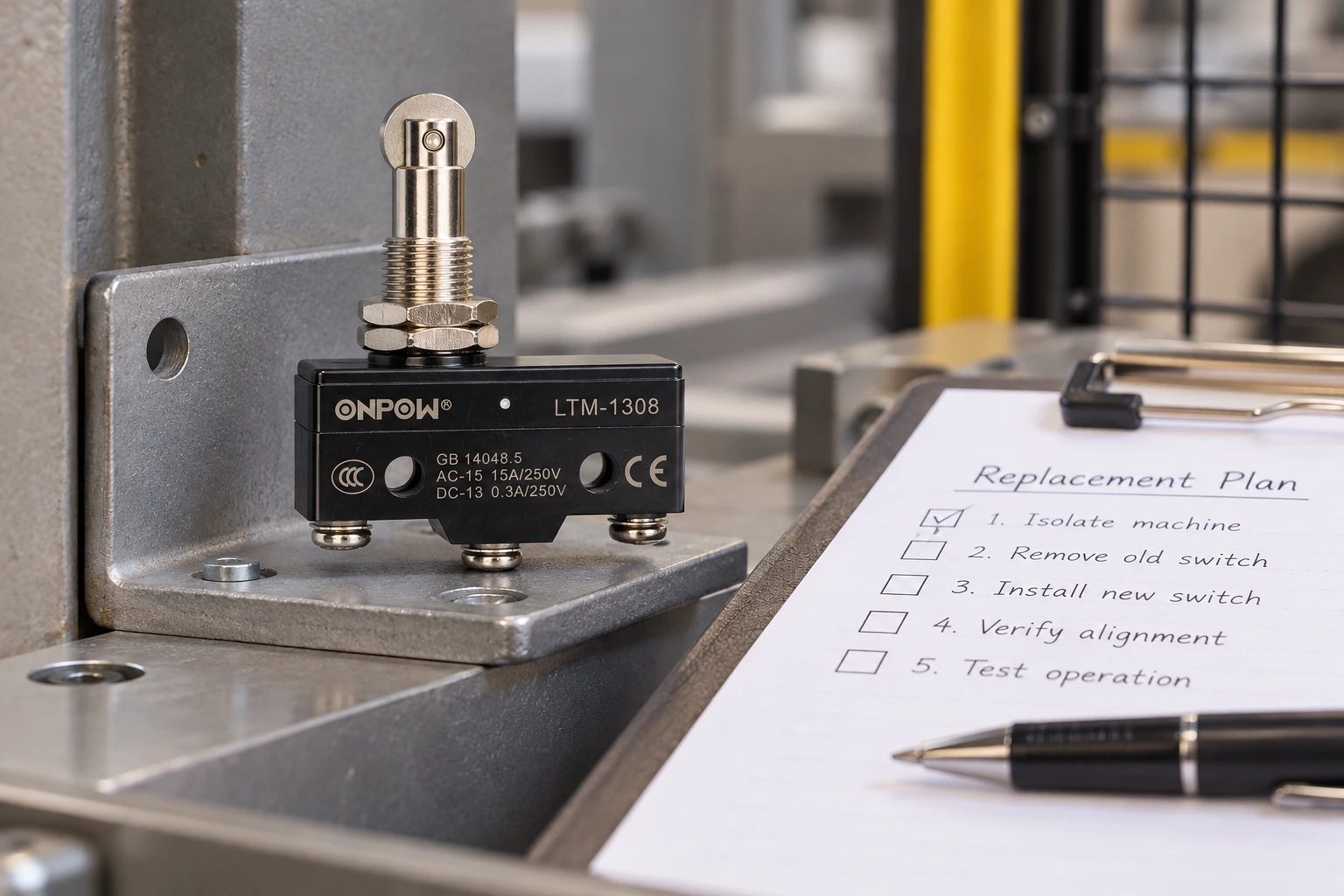
A new switch cannot correct a cracked bracket, loose fastener, damaged cam, or inadequate strain relief. Inspect these parts and compare them with the documented references. Use the manufacturer’s fastening and termination instructions for the selected replacement.
Route and support conductors so they do not pull on terminals or alter the sensor position. Keep adequate clearance from moving parts and sharp edges. Record any change to connector or terminal form, because it may affect service access and cable support even when the electrical map is unchanged.
Protect the installation from its actual environment. Review the actuator opening, body, terminals, and cable entry together. A replacement with a different sealing arrangement may require more than a matching front-body dimension. The waterproof micro switch guide discusses those installation boundaries.
Commission the replacement against the old required behavior
The acceptance reference is the machine’s documented requirement, not the behavior of a failing old switch. During the approved commissioning process, compare target position, contact state, input indication, control action, and final movement. Verify approach and release in the relevant directions.
Check permitted travel after operation and confirm that an external mechanical structure controls excessive movement where needed. Review restart, recovery, and power-restoration behavior if the signal participates in those functions. Any protective-function test must follow its required validation procedure.
Record the exact replacement suffix, drawing revision, installation setting, wiring map, measured observations, and acceptance result. If the setting or circuit changed, identify the change explicitly. Update the maintenance record and spares list so that the next replacement uses the approved variant.
A supplier enquiry that avoids another mismatch
Send the old part label, photographs, circuit drawing, bracket and target references, electrical load, operating frequency, environment, and required signal states. Explain the observed fault and whether the application is ordinary feedback or a specified protective function.
Ask the supplier to identify differences in contact behavior, mounting, force, travel, terminal form, electrical ratings, and environment. Mark unavailable information as pending. A compatibility statement should address the installation requirements rather than only saying that a product is the same size.
Обучающее видео
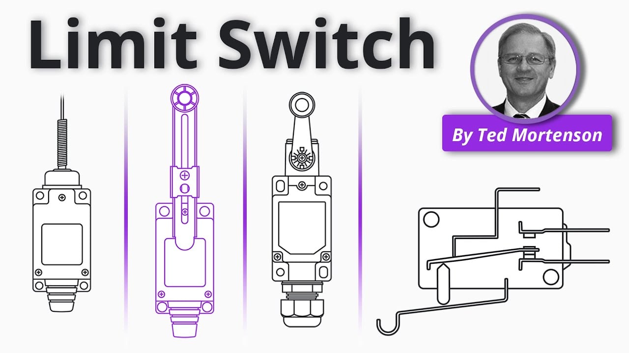
Limit Switch Explained | Working Principles by RealPars. General educational background. Use the selected product drawing and the machine design for the actual circuit and installation. Watch on YouTube.
Часто задаваемые вопросы
Can I replace a limit switch with the same terminal count?
Not on that basis alone. Contact function, terminal map, actuator, travel, mounting, ratings, environment, and the device’s role must all be compared.
Why did machine timing change after replacement?
The operating or release position may differ, or the bracket and target geometry may have shifted. Receiver filtering and control interpretation should also be checked.
Should the new switch be adjusted until it clicks?
A click alone is insufficient. The approved setting must satisfy operation, release, permitted travel, and the required machine response over relevant tolerances.
Can an ordinary micro switch replace a protective interlock?
Only the specified protective-function design and approval process can establish that substitution. Similar appearance and NC contacts do not prove suitability.
What should be kept after the job?
Keep the replacement part and drawing references, wiring map, bracket setting, fault findings, commissioning results, and any authorized installation changes.



