

AC vs DC relay coil selection depends on the coil’s specified supply waveform, voltage range, frequency where applicable, and driver requirements. A relay with AC-rated load contacts may still have a DC coil, and a DC contact rating does not identify the coil supply. Read the complete coil order code and internal circuit before selecting or replacing the unit. Do not interchange coils merely because the nominal voltage number matches. This guide focuses on the energizing coil and its control interface, including power data, suppression, noise, and replacement checks. Load-contact selection remains a separate part of the complete relay specification.
Read the coil label separately from the contact rating
An electromechanical relay uses its coil to move contacts. The coil receives the control supply; the contacts switch another circuit. Those paths can have different voltages and waveforms. A DC-powered coil can operate contacts that switch AC, subject to the contacts’ documented ratings. The opposite combination can also exist in an appropriate product.
For purchasing, record the full order code rather than a general family name or the largest voltage printed on the case. A contact label such as a rating at an AC load voltage does not authorize applying that voltage to the coil. The exact coil marking, terminal diagram, and datasheet are required to identify its supply.
This distinction matters in a cabinet with several control supplies. A machine might have an AC incoming supply, a DC controller supply, and separately powered loads. The cabinet’s main voltage does not establish the relay coil voltage. Trace the approved control circuit to the actual coil source and interface before deciding which version is needed.
Земля electromechanical relay wiring diagram guide separates the coil terminals from the switched contacts. Use that distinction throughout the specification and commissioning record so a contact-rating decision cannot silently become a coil-supply decision.
AC and DC energization create different electrical behavior
In a DC coil, the steady current is influenced by the coil resistance and temperature under its specified operating conditions. During energization and turn-off, inductance affects the current transition and voltage transient. A resistance measurement can support a component check, but it does not establish the full operating range or release behavior of the assembled relay.
An AC coil’s current also depends on inductive behavior, frequency, and the magnetic mechanism. Armature position can influence coil impedance, so some AC products specify different energizing and holding demands. Use the values provided for the actual model rather than assuming one steady-current number covers every part of its operation.
Manufacturers can design magnetic structures and internal circuits differently. Some assemblies contain rectification, indicators, or suppression that changes the interface requirements. Do not identify the internal design from a transparent case or assume a general statement about AC relays applies to every delivered version. Read the complete schematic and applicable supply specification.
Compare the information needed for each coil type
The table below describes specification questions, not a universal performance comparison. It contains no promise that one coil type is quieter, faster, or more efficient in every application. The exact relay and control circuit determine those results.
| Item | AC coil review | DC coil review | Purchasing evidence |
|---|---|---|---|
| Supply identity | Rated AC voltage and specified frequency | Rated DC voltage and polarity requirements where stated | Complete coil order code and internal circuit |
| Power demand | Use the stated VA or current data, including any separate pickup/holding values | Use the stated W or current data and operating conditions | Current datasheet and driver or transformer capacity review |
| Suppression | Manufacturer-approved AC or internally conditioned arrangement | Approved diode or other clamp arrangement, with release-time review | Socket/driver diagram and accessory identification |
| Replacement | Match supply range, frequency, interface, and mechanics | Match supply range, internal components, polarity, and mechanics | Verified replacement specification, not case resemblance |
The comparison keeps supply identity separate from performance expectations. A buyer should not request a DC relay when the intended meaning is a relay whose contacts switch a DC load. State both coil requirements and contact-load requirements explicitly so the supplier can evaluate each path.
Why the same nominal voltage does not mean interchangeability
The coil’s permitted supply range and waveform are part of its design. An AC and DC version with the same printed nominal voltage may have different winding, magnetic, power, or internal-component characteristics. Applying the other waveform can produce unsuitable current, heating, pickup, or release behavior. Do not use a quick bench click as proof of compatibility.
Check the actual supply under the operating conditions specified by the design. An unloaded reading may not represent the voltage when several coils energize together. Supply drop during startup, cable resistance, source capacity, and other connected loads can affect the voltage at the coil terminals. Any measurement on energized equipment requires the appropriate qualifications and procedure.
Where a controller output drives the coil, confirm the output’s supported load type, available current, transient protection, and connection arrangement. Where a transformer or power supply provides the coil source, review its capacity using the relay manufacturer’s demand data. Do not convert an AC VA figure directly into a DC W figure and treat the results as equivalent design approvals.
Pickup, holding, and release need their own conditions
Pickup describes the relay reaching its operated state. Holding describes maintaining that state after operation. Release describes returning from it after the energizing condition changes. These are different events, and their published values can have specified temperature, voltage, frequency, or suppression conditions.
A release-voltage statement is also different from a release-time statement. One describes an electrical threshold under specified conditions; the other describes timing. Neither should be substituted for the other when defining a machine sequence. A product’s operating-time value does not automatically describe its release after a suppressed coil is switched off.
If a process depends on timing, request the specific timing data and the test arrangement. Then evaluate the complete driver, coil, suppression, and load response under the approved commissioning method. The relay’s mechanical action is one part of the sequence; the connected contactor or machine may introduce additional behavior.
Suppression must match the coil and driver
A simple flyback diode is a familiar DC-coil arrangement, but it is not a universal AC-coil accessory. Existing sockets or relay modules may already contain an approved suppressor, rectifier, or indicator. Confirm those components before adding anything externally, and do not assume their polarity requirements from the bare coil.
Suppression can affect release behavior as well as driver voltage. The DC coil flyback-diode guide covers that separate design question. It explains why a coil diode does not automatically protect the relay’s load contacts. For the load circuit, use the appropriate contact rating and application review.
Texas Instruments’ inductive-load turn-off overview helps distinguish freewheeling paths and clamp locations. Its power-switch examples are background information, not an approved circuit for an ONPOW relay. Select the actual arrangement using the relay, socket, and driver documentation.
Interpret the published ONPOW values without extending them
Земля ORJ1SL product page lists approximately 0.53 W for DC coil power and approximately 0.9 VA for AC coil power, together with other conditions and characteristics. Those are the page’s model-family entries; confirm the exact coil version and current datasheet before sizing a supply or driver.
The figures are expressed in different quantities. They do not prove that any AC and DC versions are interchangeable or that one version is universally more efficient. The same page lists resistive contact ratings separately. Those ratings describe the load-contact path and must not be used to choose the coil supply.
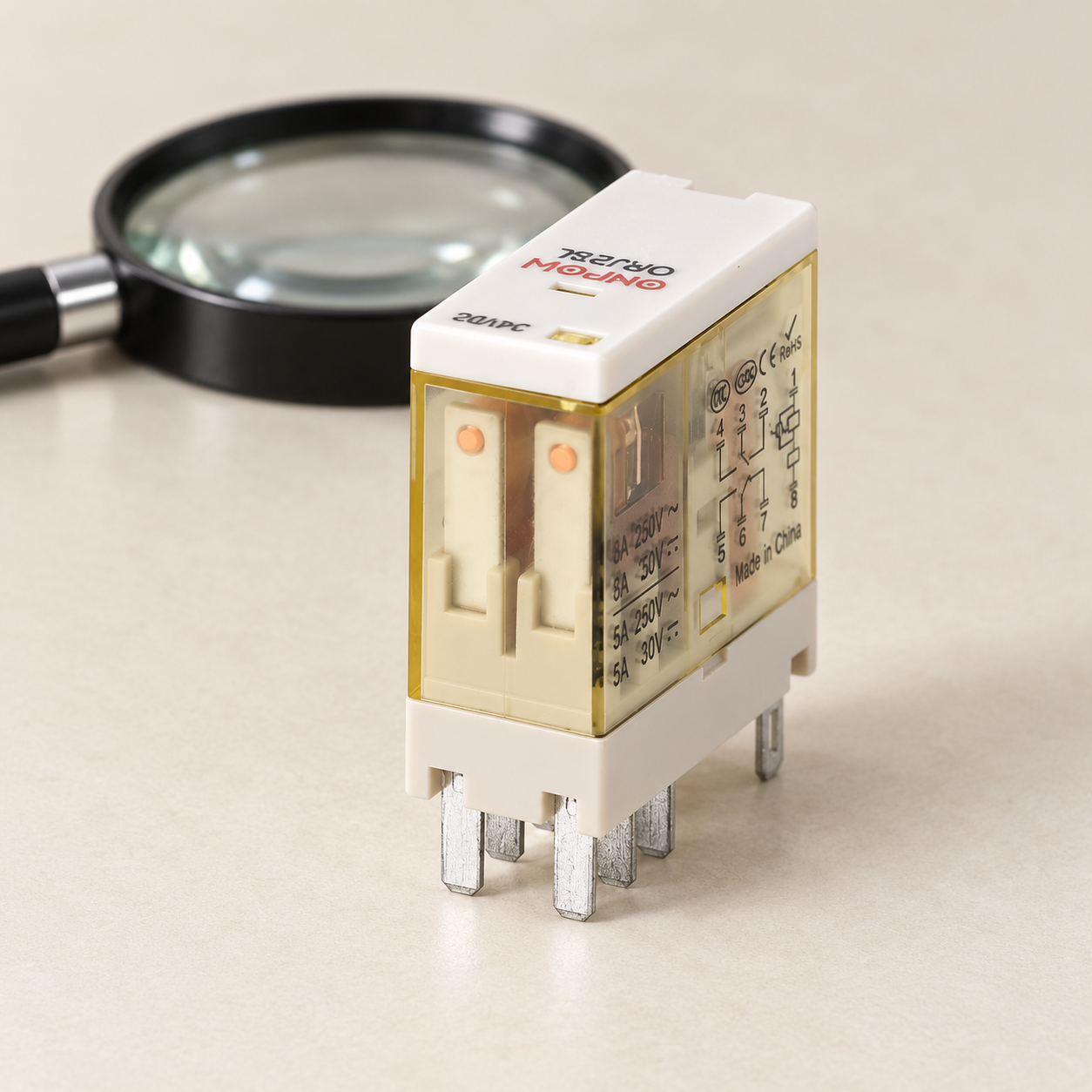
Земля ORJ2SL page is the product reference for this article’s photographs. The images show a disconnected relay for identification and inspection. A voltage marking visible on one reference unit does not establish the voltage of every order in the family. Request the complete code for the delivered device.
IEC 61810-1 provides standards context for electromechanical elementary relays. A standards page does not demonstrate conformity of a particular product or approve its use in a machine. Confirm the manufacturer’s documentation and the requirements applicable to the intended equipment and market.

Investigate chatter and heating without assuming the coil type
Chatter, failure to pick up, overheating, or an unexpected release can have several causes. A wrong coil version is one possibility, but so are unsuitable voltage at the coil, an incompatible driver, a loose connection, excessive duty, environmental conditions, or a damaged mechanism. Begin with the order code and approved schematic instead of immediately changing the coil supply.
Do not press the mechanism into position, bypass protection, or keep energizing a hot relay to see whether it settles. Follow the site’s safe-work and diagnostic procedure. 29 CFR 1910.333 describes electrical-work practices in the United States, including de-energizing and verification. Other jurisdictions and the specific machine impose their own requirements.
An isolated resistance or continuity test can identify some faults, but it cannot establish complete serviceability or rated performance. The safe relay testing guide explains those limits. Any energized diagnostic test needs an appropriate method, equipment, qualifications, and authorization under the site’s procedures.
A replacement specification should survive a future repair
Keep the complete coil code, supply type, nominal voltage, permitted range, frequency where relevant, polarity, internal accessories, socket, terminal-view direction, and operational duty in the record. Also retain the separate contact-load requirements. A case photo is useful for identification but cannot replace those electrical details.
During replacement acceptance, confirm the supplied unit against that record, then verify pickup, holding, release, and actual machine response using the approved test plan. A compatible footprint does not establish a compatible internal suppressor or operating range. Record any approved differences rather than treating them as an equivalent by default.
Земля relay selection guide covers broader contact, mechanical, and application choices. For the actual coil version, send ONPOW the proposed circuit and operating conditions and request the current model-specific evidence.
Обучающее видео
#183: Why diodes are used around relay coils: Back to Basics on flyback or snubber diodes by w2aew. This tutorial explains DC inductive turn-off. It does not approve an AC coil suppressor, a specific diode, or an ONPOW circuit. Open the video on YouTube.
Часто задаваемые вопросы
Does an AC contact rating mean the relay has an AC coil?
No. The coil supply and the load-contact rating describe different circuits. Confirm both independently from the complete order code and diagram.
Can an AC coil and a DC coil share the same nominal voltage?
They can carry the same nominal number while having different electrical requirements. That does not establish interchangeability.
Can I compare AC VA and DC W as identical power values?
No. Use each stated quantity and its operating conditions for the appropriate supply and driver review. Do not turn the numbers into a universal efficiency claim.
Is a flyback diode suitable for every relay coil?
No. A conventional flyback diode is a DC-coil arrangement. The exact AC or internally conditioned assembly needs its approved suppression method.
What matters when replacing a noisy or hot relay?
Confirm the coil version, actual supply, driver, wiring, duty, environment, and mechanism under the approved diagnostic procedure before accepting a replacement.



