

Micro switch operating force is the force required at the specified actuator point to make the contact change under the manufacturer’s stated conditions. It is not the same as release force, force at maximum travel, or an allowable impact load. Select it together with actuator geometry, target stiffness, travel, friction, and tolerance. Too little available target force can prevent operation; an excessive or poorly directed load can damage the mechanism. Operating force alone does not predict application life. A reliable installation gives the switch a controlled motion path and verifies both contact operation and release in the actual assembly.
Know which force the data sheet is reporting
The specified force belongs to a defined actuator and measurement point. A value measured at a lever end cannot be compared directly with a value at a short plunger without understanding the geometry. Different suffixes can use different actuators and internal arrangements even when the body looks similar.
Record the manufacturer’s definition of operating force, release force, and any further-travel force. Note whether the stated value is a maximum, minimum, typical value, or a range. A typical figure cannot be treated as a guaranteed maximum in a tolerance calculation. Ask for clarification if the catalogue omits the measurement position or conditions.
For the mechanism behind the force change, see how a micro switch works. For comparing actuator interfaces, use micro switch roller and cam geometry. These related subjects explain why a force number must remain attached to its physical arrangement.
Separate switch force from force at the machine target
A cam, lever, linkage, or flexible target changes the relationship between machine movement and actuator load. Friction and compliance can consume some of the available motion or force. The force required at the target is therefore not always the catalogue force applied directly at the switch’s measurement point.
For a simplified lossless lever, moment balance relates forces to their perpendicular distances from the pivot. The conceptual relationship is F1 × L1 = F2 × L2. Forces are measured in newtons and distances must use the same length unit. Real friction, changing angles, spring forces, and deformation require further analysis; this formula is not a complete installation calculation.
As an illustrative calculation unrelated to an ONPOW rating, a 2N force at a 10mm moment arm corresponds to 1N at a 20mm moment arm in an ideal static lever. That reduction in force comes with a different movement relationship. Do not change actuator length solely to reduce force without checking travel, clearance, and the manufacturer’s permitted configuration.
Build the force review around the complete stroke
The target needs sufficient force when the switch operates and enough return capability for the actuator to release. Force can change with movement as the spring mechanism passes its snap point. The final compressed position may involve a different load from the point at which the contact transfers.
| Force-related item | Question to answer | Information source |
|---|---|---|
| Operating force | Can the target reliably produce it at the specified point? | Exact actuator data and target mechanism |
| Release force | Can the target and actuator return without sticking? | Exact release data and return path |
| Further-travel load | What happens after the contact changes? | Travel/force information and external-stop design |
| Friction | Does sliding contact consume available force? | Actual target surface and geometry |
| Compliance | Does a bracket or target bend before operation? | Supported assembly measurement |
| Impact | Can the target strike the actuator unexpectedly? | Machine motion and fault analysis |
The table deliberately separates continuous actuation from impact. A static operating-force value does not establish an impact rating or permission to use the switch as a machine stop.
Low force can help a light target but creates other checks
A delicate target or low-energy mechanism may need a low-force switch so that sensing does not disturb the process. However, the installation must still cross the operating point and reset reliably. A light target can be affected by vibration, contamination, alignment, and cable or bracket movement.
Check the force over expected manufacturing and service conditions. If the target barely provides enough force at the nominal position, tolerance and friction can cause missed operation. Consider a better motion interface or an appropriate actuator option rather than choosing an unspecified lighter spring.
Do not modify the internal spring or bend the lever to achieve a desired feel unless the manufacturer’s instructions explicitly permit the method. Such changes can alter travel, contact timing, and life. Obtain an approved variant whose published characteristics can be assessed.
Higher force is not automatically longer life
Mechanical life is associated with declared test conditions and component behavior. Electrical life depends on the load and switching conditions as well. A force number by itself does not reveal either result in a real mechanism. A higher-force switch subjected to side rubbing or excessive travel can still fail early.
A larger applied target force can increase bracket movement, wear at the contact surface, and stress at a fastener. Where the machine target continues beyond the necessary stroke, an external stop or a suitable cam arrangement should control that movement. Do not treat the switch’s body or plunger as an unlimited structural element.
The standards context in IEC 60947-5-1 does not supply a universal force-to-life equation. Request the exact model’s declared mechanical and electrical data, and verify the application conditions separately.
Side loading and mounting flexibility change the result
A pin plunger generally needs the allowed substantially axial actuation. A lever or roller has its own permitted direction and geometry. Off-axis contact can increase friction, inhibit reset, or wear the actuator even when the nominal push force seems suitable.
Bracket flex is another common source of misleading measurements. Part of the target’s motion can bend the bracket before it moves the actuator. A hand-operated test on a loose bench part does not reproduce that installation. Measure the supported assembly with the target in its actual motion path.
Check fastening, adjustment locks, and cable strain relief. A moving harness can shift the switch or pull on its mounting. Use the industrial micro switch selection checklist to include these mechanical details alongside contact rating and environment.
Measure force without exceeding permitted travel
Use an appropriate measurement method defined by the engineering test plan. Place the force instrument at the specified contact point and align it with the permitted direction. Record the actuator position and the electrical change, not only the largest reading seen during an uncontrolled push.
If the test continues beyond operation, remain inside the specified travel and load limits. A force gauge does not make an overload test harmless. Repeatedly pressing a small actuator hard against its internal end position can damage the component and invalidate the comparison.
For installed equipment, inspection and testing must follow the machine’s energy-control procedure. Qualified personnel should consider electrical and stored-energy hazards. United States requirements include 29 CFR 1910.147 и 29 CFR 1910.333. Use the authorized commissioning procedure for any powered test.
Look at application life through the actual failure mechanism
If switches are failing early, examine the damage and operating conditions before changing the force specification. A worn contact surface suggests a different problem from a burnt electrical contact, bent actuator, loose bracket, cracked body, or intermittent terminal. Several can coexist.
Compare switching load, frequency, target speed, maximum travel, direction of force, environment, and the timing of failures. A contact problem under an inductive load may need electrical-interface review rather than a lighter actuator. A mechanically damaged plunger may need the cam or external stop corrected.
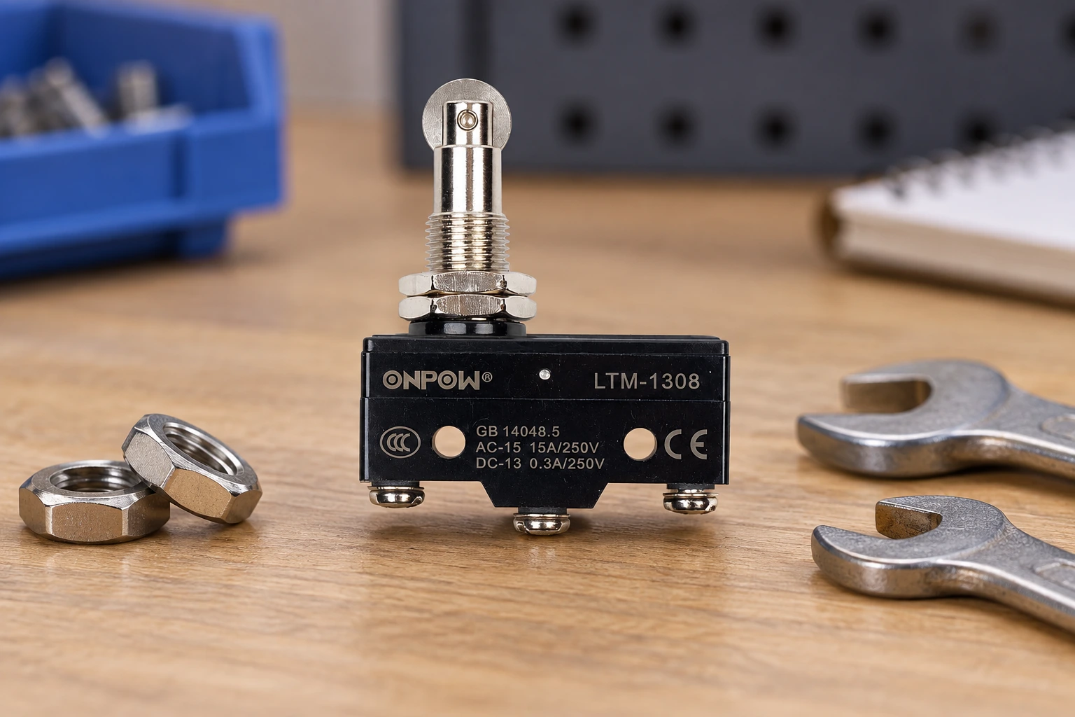
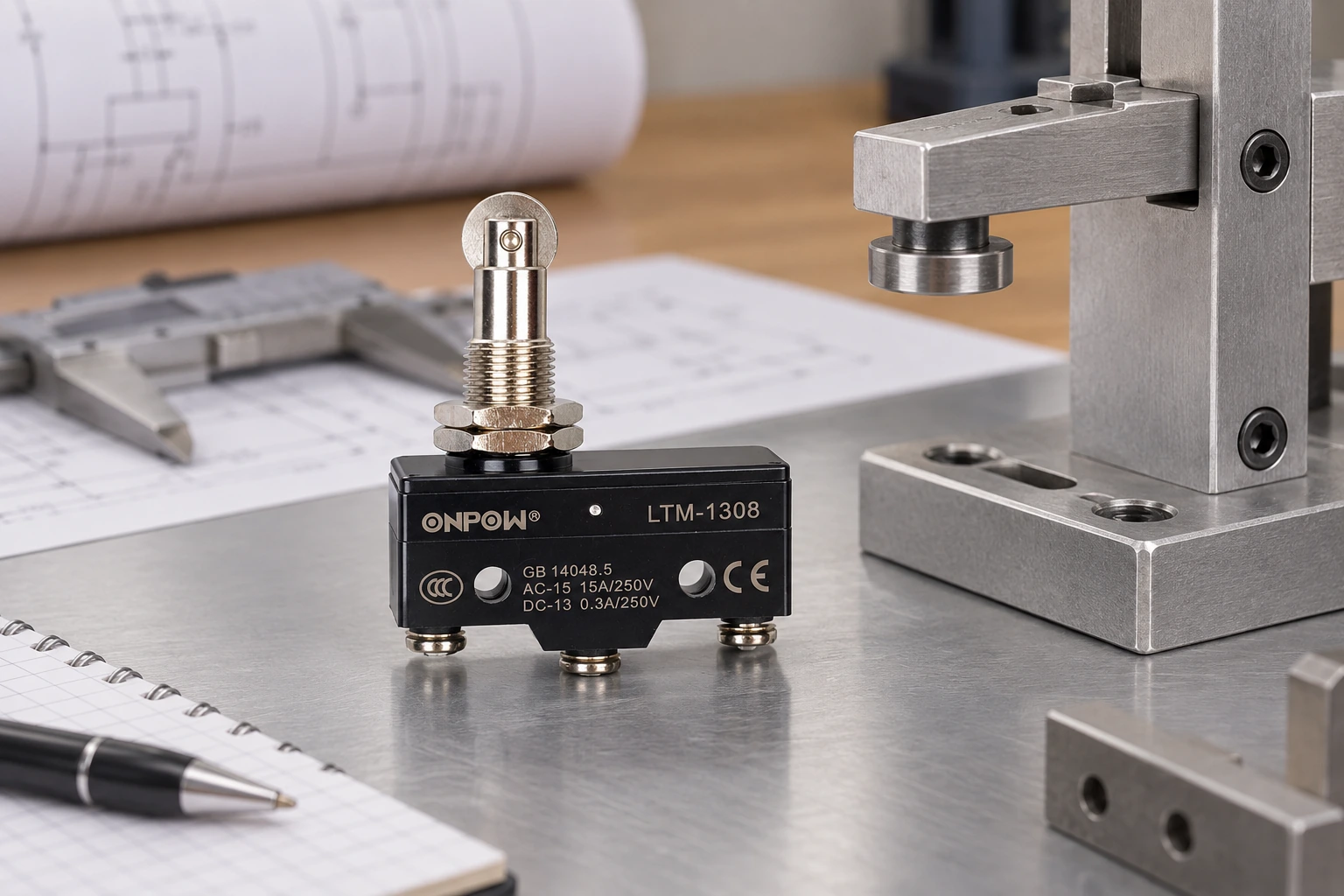
A real ONPOW LTM-1308 product example appears in the illustrations. The image does not establish its force or life in your application. Request current force and travel data for the exact variant and send photographs of the mechanism when discussing early wear.
Specify force with measurable acceptance conditions
A supplier enquiry should identify actuator type, measurement point, target-motion range, available force, operating frequency, environment, electrical load, and mounting arrangement. Include the target’s tolerance and any risk of side loading or impact. State the required operating and release behavior.
In the final specification, distinguish guaranteed limits from typical catalogue values. Record the acceptance test and the installed adjustment reference. If application life is important, define the actual qualification conditions rather than substituting the catalogue’s mechanical-cycle figure for a field-life promise.
Используйте micro switch versus limit-switch comparison when deciding whether the application needs a bare component or a more complete position-sensing assembly with different mounting and protection requirements.
Обучающее видео
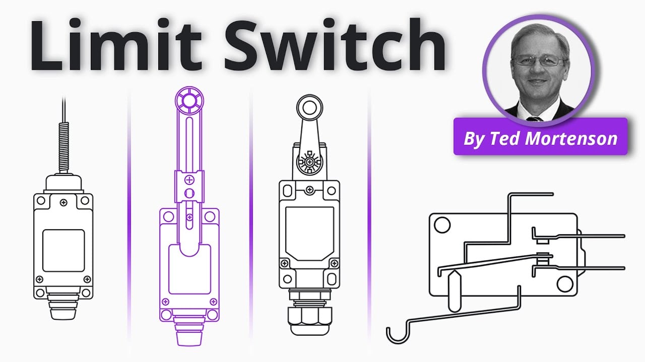
Limit Switch Explained | Working Principles by RealPars. General educational background. Use the selected product drawing and the machine design for the actual circuit and installation. Watch on YouTube.
Часто задаваемые вопросы
Is operating force the force needed for the entire stroke?
No general assumption allows that interpretation. It refers to the defined contact-operation condition. Force at further travel and the permitted end position must be checked separately.
Can a longer lever reduce the target force?
It can change the force relationship, but it also changes movement, clearance, and geometry. Use an approved actuator option and verify the complete mechanism.
Does lower force mean faster electrical switching?
Not by itself. Electrical transfer, actuator movement, and receiver timing are separate characteristics. Verify the specific component and application rather than inferring speed from force.
Can operating force predict service life?
No. Load, travel, alignment, switching conditions, frequency, environment, and mechanical support also influence the result. Use declared data and application qualification.
What should be recorded during a force test?
Record the exact part, actuator, measurement point and direction, operating and release positions, observed forces, fixture arrangement, and applicable acceptance limits.



