

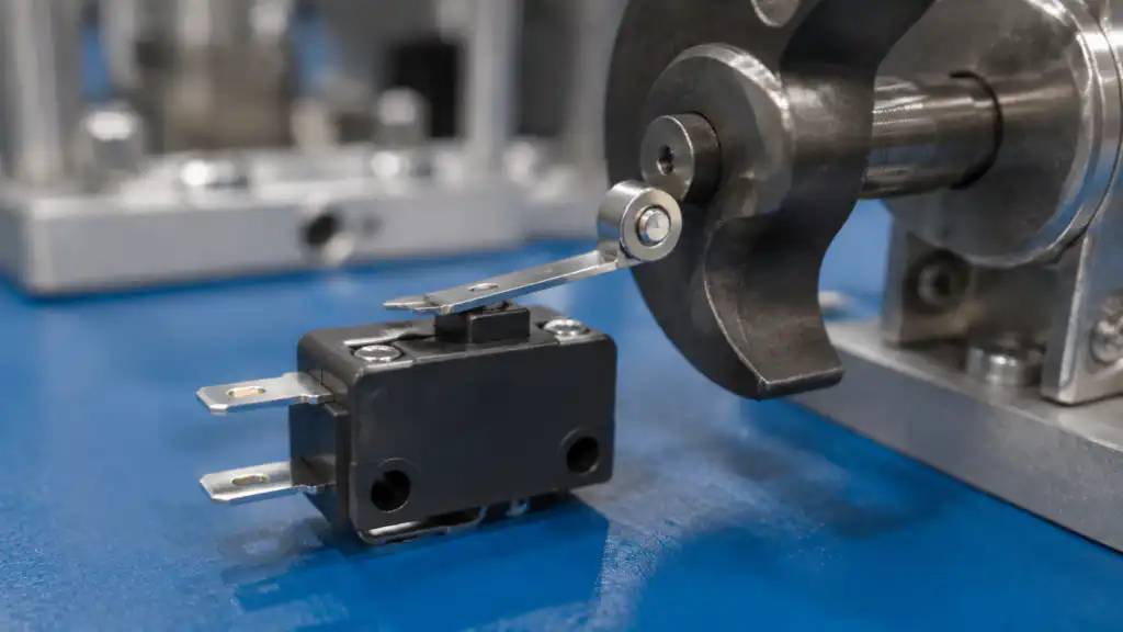
A micro switch roller is used when a moving target or cam needs to pass across the actuator with less sliding friction than a plain lever or plunger. Roller plunger and roller lever designs behave differently: the plunger accepts mainly axial force, while a lever changes reach, force, and travel before moving the internal mechanism. Select the arrangement from the actual motion path and tolerance stack. Verify roller diameter, lever geometry, operating force, pretravel, overtravel, release point, speed, mounting, and environmental limits for the exact order code.
Auswahlregel: Betrachten Sie das Gerät, den Aktor, die Kontakte, das Gehäuse, die Verdrahtung, die Steuerungslogik, den Benutzer und die Maschinenbewegung als ein einziges System. Produktbeispiele veranschaulichen lediglich die Bauform; die endgültige Eignung muss sich aus der aktuellen Dokumentation für die genaue Bestellnummer und aus der Validierung in der fertigen Ausrüstung ergeben.
Wie der Mechanismus funktioniert
The roller rotates at the cam interface while the plunger or lever transfers motion to the snap mechanism. On a lever, contact at a larger radius generally changes the travel and force relationship at the internal plunger. Moving the cam contact point or changing the approach angle can therefore alter effective operation. The roller reduces rubbing but does not eliminate bearing wear, impact, contamination, or misalignment.

Auswahlkriterien auf einen Blick
| Entscheidungsbereich | Was zu überprüfen ist | technischer Grund |
|---|---|---|
| Roller arrangement | Choose roller plunger for direct stroke or roller lever for side-travel reach | The two forms transmit motion differently. |
| Cam direction | Follow the permitted approach shown in the drawing | Reverse or side impact may bend the lever or bind the plunger. |
| Contact radius | Keep the cam on the intended roller track | Off-center contact can create uneven wear. |
| Lever length | Use the documented geometry and adjustment range | Length changes effective force and movement. |
| Operating margin | Cross the operating point under every tolerance condition | Nominal operation can hide missed signals. |
| Release margin | Ensure the cam retreats far enough for reset | Incomplete release can leave the circuit in the wrong state. |
| Speed and impact | Use a smooth profile and permitted operating speed | The roller is not an impact absorber. |
| Contamination | Consider chips, fibers, dust, oil, and moisture at the roller | Debris can stop rotation or alter the motion path. |
Diese Tabelle ist absichtlich qualitativ gehalten. Numerische Grenzwerte, Nennwerte, Drehmoment, Kraft, Verfahrweg, Umwelteinflüsse und Haltbarkeitswerte müssen dem aktuellen Datenblatt entnommen und unter den Anwendungsbedingungen bewertet werden.
Detaillierter Auswahlprozess
Roller arrangement
Was zu überprüfen ist: Choose roller plunger for direct stroke or roller lever for side-travel reach. The two forms transmit motion differently. The requirement should be written in the project specification and traced to the exact model drawing or datasheet. Review worst-case tolerance, wear, contamination, maintenance access, and foreseeable misuse. If the available documentation does not define the boundary, keep the point open for supplier confirmation and sample testing rather than substituting an assumption.
Cam direction
Was zu überprüfen ist: Follow the permitted approach shown in the drawing. Reverse or side impact may bend the lever or bind the plunger. The requirement should be written in the project specification and traced to the exact model drawing or datasheet. Review worst-case tolerance, wear, contamination, maintenance access, and foreseeable misuse. If the available documentation does not define the boundary, keep the point open for supplier confirmation and sample testing rather than substituting an assumption.
Contact radius
Was zu überprüfen ist: Keep the cam on the intended roller track. Off-center contact can create uneven wear. The requirement should be written in the project specification and traced to the exact model drawing or datasheet. Review worst-case tolerance, wear, contamination, maintenance access, and foreseeable misuse. If the available documentation does not define the boundary, keep the point open for supplier confirmation and sample testing rather than substituting an assumption.
Lever length
Was zu überprüfen ist: Use the documented geometry and adjustment range. Length changes effective force and movement. The requirement should be written in the project specification and traced to the exact model drawing or datasheet. Review worst-case tolerance, wear, contamination, maintenance access, and foreseeable misuse. If the available documentation does not define the boundary, keep the point open for supplier confirmation and sample testing rather than substituting an assumption.
Operating margin
Was zu überprüfen ist: Cross the operating point under every tolerance condition. Nominal operation can hide missed signals. The requirement should be written in the project specification and traced to the exact model drawing or datasheet. Review worst-case tolerance, wear, contamination, maintenance access, and foreseeable misuse. If the available documentation does not define the boundary, keep the point open for supplier confirmation and sample testing rather than substituting an assumption.
Release margin
Was zu überprüfen ist: Ensure the cam retreats far enough for reset. Incomplete release can leave the circuit in the wrong state. The requirement should be written in the project specification and traced to the exact model drawing or datasheet. Review worst-case tolerance, wear, contamination, maintenance access, and foreseeable misuse. If the available documentation does not define the boundary, keep the point open for supplier confirmation and sample testing rather than substituting an assumption.
Speed and impact
Was zu überprüfen ist: Use a smooth profile and permitted operating speed. The roller is not an impact absorber. The requirement should be written in the project specification and traced to the exact model drawing or datasheet. Review worst-case tolerance, wear, contamination, maintenance access, and foreseeable misuse. If the available documentation does not define the boundary, keep the point open for supplier confirmation and sample testing rather than substituting an assumption.
Contamination
Was zu überprüfen ist: Consider chips, fibers, dust, oil, and moisture at the roller. Debris can stop rotation or alter the motion path. The requirement should be written in the project specification and traced to the exact model drawing or datasheet. Review worst-case tolerance, wear, contamination, maintenance access, and foreseeable misuse. If the available documentation does not define the boundary, keep the point open for supplier confirmation and sample testing rather than substituting an assumption.

Bewerbungsprüfung
- Cam-operated sequence detection. Record the expected command, response, release behavior, abnormal condition, and acceptance evidence for the assembled machine.
- Conveyor product sensing with controlled contact. Record the expected command, response, release behavior, abnormal condition, and acceptance evidence for the assembled machine.
- Machine home-position feedback. Record the expected command, response, release behavior, abnormal condition, and acceptance evidence for the assembled machine.
- Door or tray position inside equipment. Record the expected command, response, release behavior, abnormal condition, and acceptance evidence for the assembled machine.
- Repeated indexing where a rolling interface reduces wear. Record the expected command, response, release behavior, abnormal condition, and acceptance evidence for the assembled machine.
Für jede Anwendung sind der Anlauf, der Normalbetrieb, das Herunterfahren, der Stromausfall, die Wiederherstellung der Stromversorgung, der Wartungsmodus, der Austausch von Komponenten und die durch die Risikobeurteilung identifizierten Fehler einzubeziehen. Ein allgemeiner Steuerschalter sollte nicht als vollständige Sicherheitsfunktion betrachtet werden.
Inbetriebnahme-Checkliste
- Die Anforderung einfrieren. Geben Sie die beabsichtigte Aktion, den Normalzustand, die Versorgung, die Last, die Bewegung, die Umgebung und den Benutzer an.
- Den Bestellcode zuordnen. Vergleichen Sie das gelieferte Teil mit der genehmigten Zeichnung, dem Kontaktdiagramm, dem Antrieb, der Anschlusstechnik und dem Zubehör.
- Installation inspizieren. Überprüfen Sie Ausrichtung, Befestigungselemente, hinteren Freiraum, Kabelführung, Zugentlastung, Schutz von unter Spannung stehenden Teilen und den Servicezugang.
- Teste jeden Staat. Überprüfen Sie Funktion und Auslösung bei Toleranzextremen, erwarteten Geschwindigkeiten, Lasten, Handschuhen, Verschmutzung und Umgebungsbedingungen.
- Teste anormale Zustände. Schließen Sie getrennte Leiter, blockierte oder beschädigte Mechanismen, Stromausfall, Verschmutzung und andere plausible Fehler ein.
- Ergebnis aufzeichnen. Speichern Sie Modell, Revisionsstand, Testmethode, Beobachtungen, Annahmekriterien, Datum und Genehmigenden.
Common mistakes
- Letting the cam run off the roller edge. Prevent this by assigning the check to a drawing, datasheet, wiring record, or commissioning test with a named acceptance criterion.
- Bending a lever to compensate for mounting error. Prevent this by assigning the check to a drawing, datasheet, wiring record, or commissioning test with a named acceptance criterion.
- Ignoring the release direction. Prevent this by assigning the check to a drawing, datasheet, wiring record, or commissioning test with a named acceptance criterion.
- Assuming a larger roller always improves repeatability. Prevent this by assigning the check to a drawing, datasheet, wiring record, or commissioning test with a named acceptance criterion.
- Using the actuator as a hard stop. Prevent this by assigning the check to a drawing, datasheet, wiring record, or commissioning test with a named acceptance criterion.
What to include in an RFQ
Provide the application, target market, applicable standards, machine function, supply and load, control interface, contact logic, mechanical drawing, motion path, panel dimensions, cable method, environment, operating frequency, quantity, documentation needs, and sample-validation plan. Ask the supplier to identify assumptions and exceptions. ONPOW offers relevant products in its application-specific product family and the broader industrial control product range.
Related ONPOW guides
Authoritative references
- IEC 60947-5-1 control-circuit devices
- IEC 60529 degrees of protection provided by enclosures
- OSHA machine guarding requirements
- OSHA electrical safety requirements
Educational video
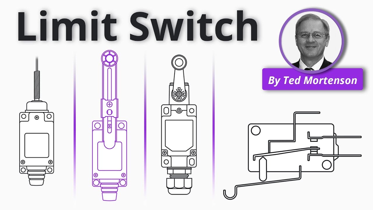
Limit Switch Explained by RealPars provides general background. Project decisions still require the applicable standards and product documentation.
Allgemeine Fragen
What is the difference between a roller lever and roller plunger?
A roller lever pivots and changes mechanical leverage; a roller plunger moves primarily along its axis.
Does the roller reduce operating force?
The effect depends on the complete lever geometry and switch design; use the exact force and travel data.
Can the lever be bent during installation?
Do not modify it unless the manufacturer explicitly permits an adjustment method.
How is wear checked?
Inspect roller rotation, surface condition, lever alignment, mounting security, operating point, and reliable electrical change.
Final decision
Approve the component only when the documented mechanical, electrical, environmental, usability, installation, and maintenance boundaries all fit the assembled system. Resolve unknowns through current manufacturer information and testing before production release.
Anpassung
ONPOW undertakes a variety of custom needs for push-button development. Confirm whether packaging, marking or documentation OEM/ODM applies to Micro Switch Roller Selection: Lever, Plunger, and Cam Geometry in the quotation.
Die Mindestbestellmenge, die Lieferzeit und die Handelsbedingungen werden hier nicht veröffentlicht; bestätigen Sie diese bei der Vertriebsabteilung. sales@onpow.com.



