

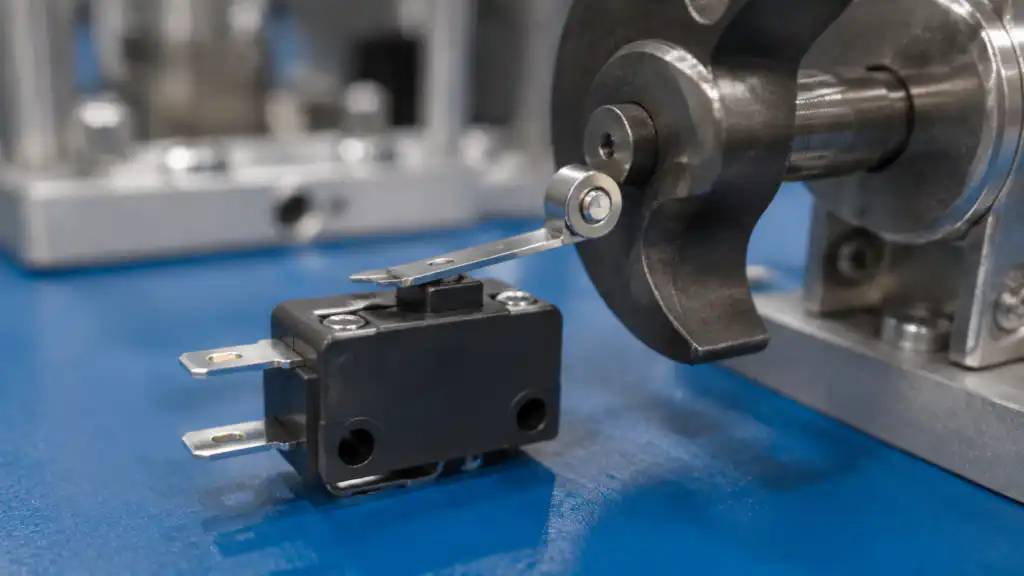
Un microrupteur à galet est utilisé lorsqu'une cible mobile ou une came doit passer sur l'actionneur avec moins de frottement de glissement qu'avec un levier simple ou un poussoir. Les conceptions à poussoir à galet et à levier à galet se comportent différemment : le poussoir accepte principalement une force axiale, tandis qu'un levier modifie la portée, la force et la course avant d'actionner le mécanisme interne. Sélectionnez la disposition en fonction de la trajectoire de mouvement réelle et de la chaîne de tolérances. Vérifiez le diamètre du galet, la géométrie du levier, la force d'actionnement, la pré-course, la course de dépassement, le point de relâchement, la vitesse, le montage et les limites environnementales pour le code de commande exact.
Règle de sélection : traitez l'appareil, l'actionneur, les contacts, le boîtier, le câblage, la logique de commande, l'utilisateur et le mouvement de la machine comme un seul système. Les exemples de produits n'illustrent que la forme ; l'aptitude finale doit provenir de la documentation actuelle pour le code de commande exact et de la validation dans l'équipement fini.
Comment fonctionne le mécanisme
Le galet tourne au niveau de l'interface de la came tandis que le plongeur ou le levier transmet le mouvement au mécanisme à action instantanée. Sur un levier, un contact à un rayon plus grand modifie généralement la relation entre la course et la force au niveau du plongeur interne. Déplacer le point de contact de la came ou modifier l'angle d'approche peut donc altérer le fonctionnement effectif. Le galet réduit les frottements mais n'élimine pas l'usure des paliers, les chocs, la contamination ou le désalignement.

Critères de sélection en un coup d'œil
| Zone de décision | Que vérifier | Raison technique |
|---|---|---|
| Agencement des galets | Choisissez le piston à galet pour une course directe ou le levier à galet pour un accès par déplacement latéral | Les deux formes transmettent le mouvement différemment. |
| Direction de la came | Suivez l'approche autorisée indiquée sur le dessin | Un choc arrière ou latéral peut tordre le levier ou bloquer le piston. |
| Rayon de contact | Gardez la came sur le chemin de roulement prévu | Un contact excentré peut créer une usure irrégulière. |
| Longueur du levier | Utiliser la géométrie documentée et la plage de réglage | La longueur modifie la force effective et le mouvement. |
| Marge opérationnelle | Franchir le point de fonctionnement dans toutes les conditions de tolérance | Le fonctionnement nominal peut masquer des signaux manqués. |
| Marge de dégagement | Assurez-vous que la cague recule suffisamment pour la réinitialisation | Un relâchement incomplet peut laisser le circuit dans le mauvais état. |
| Vitesse et impact | Utilisez un profil régulier et la vitesse de fonctionnement autorisée | Le rouleau n'est pas un absorbeur de chocs. |
| Contamination | Considérez les copeaux, les fibres, la poussière, l'huile et l'humidité au niveau du rouleau | Des débris peuvent arrêter la rotation ou altérer la trajectoire de mouvement. |
Ce tableau est intentionnellement qualitatif. Les limites numériques, les valeurs nominales, le couple, la force, la course, les déclarations environnementales et les valeurs d'endurance doivent être tirés de la fiche technique actuelle et évalués dans les conditions de l'application.
Processus de sélection détaillé
Agencement des galets
À vérifier : Choisissez un poussoir à galet pour une course directe ou un levier à galet pour une approche par le côté. Les deux formes transmettent le mouvement différemment. L'exigence doit être rédigée dans le cahier des charges du projet et rattachée au dessin de modèle ou à la fiche technique exact. Examinez la tolérance au pire cas, l'usure, la contamination, l'accès à la maintenance et les utilisations abusives prévisibles. Si la documentation disponible ne définit pas la limite, laissez le point ouvert pour confirmation par le fournisseur et test d'échantillons plutôt que de substituer une supposition.
Direction de la came
À vérifier : Suivez l'approche autorisée indiquée sur le dessin. Un choc arrière ou latéral risque de tordre le levier ou de gripper le piston. L'exigence doit être rédigée dans le cahier des charges du projet et rattachée au dessin du modèle exact ou à la fiche technique. Examinez la tolérance au pire cas, l'usure, la contamination, l'accès pour la maintenance et les utilisations abusives prévisibles. Si la documentation disponible ne définit pas la limite, laissez le point ouvert pour confirmation par le fournisseur et test d'échantillons plutôt que de substituer une supposition.
Rayon de contact
À vérifier : Gardez la came sur la piste de roulement prévue. Un contact excentré peut entraîner une usure inégale. Cette exigence doit être rédigée dans le cahier des charges du projet et rattachée au dessin de modèle exact ou à la fiche technique. Examinez la tolérance au pire cas, l'usure, la contamination, l'accès à la maintenance et l'utilisation abusive prévisible. Si la documentation disponible ne définit pas la limite, laissez le point ouvert pour confirmation par le fournisseur et tests d'échantillons plutôt que de substituer une supposition.
Longueur du levier
À vérifier : Utiliser la géométrie documentée et la plage de réglage. La modification de la longueur influe sur la force effective et le mouvement. L'exigence doit être consignée dans le cahier des charges du projet et rattachée au dessin de modélisation exact ou à la fiche technique. Examiner la tolérance au pire cas, l'usure, la contamination, l'accès à la maintenance et l'utilisation détournée prévisible. Si la documentation disponible ne définit pas la limite, laisser le point ouvert pour confirmation par le fournisseur et test d'échantillons plutôt que de substituer une hypothèse.
Marge opérationnelle
À vérifier : Franchir le point de fonctionnement dans toutes les conditions de tolérance. Le fonctionnement nominal peut masquer des signaux manqués. L'exigence doit être rédigée dans le cahier des charges du projet et liée au dessin du modèle ou à la fiche technique exacts. Examiner la tolérance au pire cas, l'usure, la contamination, l'accès pour la maintenance et l'usage détourné prévisible. Si la documentation disponible ne définit pas la limite, laisser le point ouvert pour confirmation par le fournisseur et essais sur échantillons plutôt que de substituer une hypothèse.
Marge de dégagement
À vérifier : Assurez-vous que la came recule suffisamment pour la réinitialisation. Un relâchement incomplet peut laisser le circuit dans le mauvais état. L'exigence doit être écrite dans le spécification du projet et tracée jusqu'au dessin de modèle exact ou à la fiche technique. Examinez la tolérance au pire cas, l'usure, la contamination, l'accès à la maintenance et l'utilisation abusive prévisible. Si la documentation disponible ne définit pas la limite, laissez le point ouvert pour confirmation par le fournisseur et test d'échantillons plutôt que de substituer une hypothèse.
Vitesse et impact
À vérifier : Utiliser un profil régulier et la vitesse de fonctionnement autorisée. Le galet n'est pas un absorbeur de chocs. L'exigence doit être rédigée dans le cahier des charges du projet et liée au dessin de modèle exact ou à la fiche technique. Examiner la tolérance au pire cas, l'usure, la contamination, l'accès à la maintenance et l'utilisation détournée prévisible. Si la documentation disponible ne définit pas la limite, laisser le point ouvert pour confirmation par le fournisseur et essais sur échantillons plutôt que de substituer une hypothèse.
Contamination
À vérifier : Considérez les copeaux, les fibres, la poussière, l'huile et l'humidité au niveau du rouleau. Les débris peuvent arrêter la rotation ou altérer la trajectoire du mouvement. L'exigence doit être rédigée dans le cahier des charges du projet et rattachée au dessin de modèle exact ou à la fiche technique. Examinez la tolérance au pire cas, l'usure, la contamination, l'accès à la maintenance et l'utilisation détournée prévisible. Si la documentation disponible ne définit pas la limite, laissez le point ouvert pour confirmation par le fournisseur et tests d'échantillons plutôt que de substituer une supposition.

Examen de la demande
- Détection de séquence commandée par cames. Enregistrer la commande attendue, la réponse, le comportement de relâchement, la condition anormale et les preuves de recette pour la machine assemblée.
- Détection de produits sur convoyeur avec contact contrôlé. Enregistrer la commande attendue, la réponse, le comportement de libération, la condition anormale et les preuves de recette pour la machine assemblée.
- Retour à la position d'origine de la machine. Enregistrer la commande attendue, la réponse, le comportement de libération, la condition anormale et la preuve de recette pour la machine assemblée.
- Position de la porte ou du plateau à l'intérieur de l'équipement. Enregistrer la commande attendue, la réponse, le comportement de libération, la condition anormale et la preuve d'acceptation pour la machine assemblée.
- Indexage répété où une interface roulante réduit l'usure. Enregistrer la commande attendue, la réponse, le comportement de libération, la condition anormale et la preuve de conformité pour la machine assemblée.
Pour chaque application, inclure le démarrage, le fonctionnement normal, l'arrêt, la perte de courant, le rétablissement du courant, le mode de maintenance, le remplacement de composants et les défauts identifiés par l'évaluation des risques. Un interrupteur de commande général ne doit pas être considéré comme une fonction de sécurité complète.
Liste de contrôle de mise en service
- Geler le besoin. Indiquer l'action prévue, la condition normale, l'alimentation, la charge, le mouvement, l'environnement et l'utilisateur.
- Faites correspondre le code de commande. Comparez la pièce livrée avec le dessin approuvé, le schéma de contacts, l'actionneur, le style de borne et les accessoires.
- Inspecter l'installation. Vérifier l'alignement, les éléments de fixation, le dégagement arrière, le cheminement des câbles, le soulagement de traction, la protection des pièces sous tension et l'accès pour l'entretien.
- Tester chaque état. Vérifier le fonctionnement et le déclenchement aux extrêmes de tolérance, aux vitesses prévues, aux charges, avec des gants, en présence de contamination et dans diverses conditions environnementales.
- Tester les conditions anormales. Inclure les conducteurs débranchés, les mécanismes bloqués ou endommagés, la perte d'alimentation, la contamination et autres défauts crédibles.
- Enregistrez le résultat. Enregistrer le modèle, la révision, la méthode d'essai, les observations, les critères d'acceptation, la date et l'approbateur.
Erreurs courantes
- Laisser la came dépasser du bord du galet. Prévenez cela en affectant la vérification à un dessin, une fiche technique, un schéma de câblage ou un essai de mise en service avec un critère d'acceptation nommé.
- Tordre un levier pour compenser une erreur de montage. Prévenez cela en affectant la vérification à un dessin, une fiche technique, un schéma de câblage ou un essai de mise en service avec un critère d'acceptation nommé.
- En faisant abstraction de la direction de diffusion. Prévenez cela en affectant la vérification à un dessin, une fiche technique, un schéma de câblage ou un essai de mise en service avec un critère d'acceptation nommé.
- En supposant qu'un galet plus grand améliore toujours la répétabilité. Prévenez cela en affectant la vérification à un dessin, une fiche technique, un schéma de câblage ou un essai de mise en service avec un critère d'acceptation nommé.
- Utiliser l'actionneur comme butée mécanique. Prévenez cela en affectant la vérification à un dessin, une fiche technique, un schéma de câblage ou un essai de mise en service avec un critère d'acceptation nommé.
Que faut-il inclure dans une demande de prix
Fournissez l'application, le marché cible, les normes applicables, la fonction de la machine, l'alimentation et la charge, l'interface de commande, la logique de contact, le dessin mécanique, la trajectoire de mouvement, les dimensions du panneau, la méthode de câblage, l'environnement, la fréquence de fonctionnement, la quantité, les besoins en documentation et le plan de validation des échantillons. Demandez au fournisseur d'identifier les hypothèses et les exceptions. ONPOW propose des produits pertinents dans sa famille de produits spécifique à une application et le plus large gamme de produits de contrôle industriel.
Guides ONPOW associés
- Comment fonctionne un micro-interrupteur
- Micro-interrupteur vs fin de course
- Vie mécanique contre vie électrique
Références autorisées
- appareils de circuit de commande CEI 60947-5-1
- CEI 60529 degrés de protection procurés par les enveloppes
- Exigences d'OSHA concernant la protection des machines
- Exigences de sécurité électrique de l'OSHA
Vidéo éducative
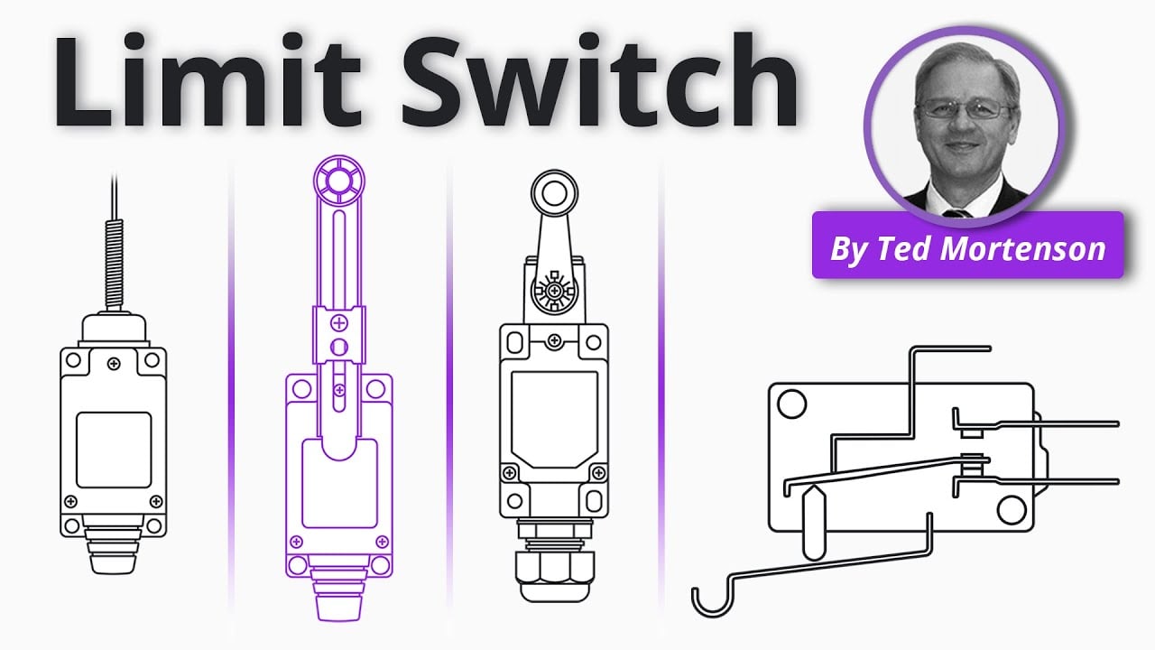
Limit Switch Explained par RealPars fournit un contexte général. Les décisions de projet nécessitent toujours les normes applicables et la documentation du produit.
Foire aux questions
Quelle est la différence entre un levier à galet et un poussoir à galet ?
Un levier à galet pivote et modifie l'avantage mécanique ; un poussoir à galet se déplace principalement le long de son axe.
Le galet réduit-il la force de fonctionnement ?
L'effet dépend de la géométrie complète du levier et de la conception de l'interrupteur ; utilisez les données exactes de force et de course.
Le levier peut-il être tordu lors de l'installation ?
Ne le modifiez pas à moins que le fabricant n'autorise explicitement une méthode de réglage.
Comment vérifie-t-on l'usure ?
Inspecter la rotation du galet, l'état de surface, l'alignement du levier, la sécurité de la fixation, le point de fonctionnement et la commutation électrique fiable.
Décision finale
Approuvez le composant uniquement lorsque les limites documentées relatives à la mécanique, à l'électricité, à l'environnement, à l'ergonomie, à l'installation et à la maintenance correspondent toutes au système assemblé. Résolvez les inconnues grâce aux informations actuelles du fabricant et à des tests avant le lancement de la production.
Personnalisation
ONPOW undertakes a variety of custom needs for push-button development. Confirm whether packaging, marking or documentation OEM/ODM applies to Micro Switch Roller Selection: Lever, Plunger, and Cam Geometry in the quotation.
La quantité minimale d’ordre, le délai de livraison et les modalités commerciales ne sont pas indiqués ici ; veuillez les confirmer auprès de la direction commerciale. sales@onpow.com.



