

Use a steady indicator light for a condition that operators need to read continuously, and use a flashing indication when a defined event needs attention within the equipment’s alarm strategy. Flashing is not automatically more informative or safer. Its meaning, priority, acknowledgement, return to steady state, and operator action must be documented. Check visibility at the actual viewing distance and ambient light, and confirm that the selected lamp and controller can produce the required behavior. A normal pilot lamp does not acquire a flashing function merely because it is connected to a PLC output.
Start with the operator’s required response
List the machine conditions that need an indication and the action expected for each. Running, ready, waiting, fault, and acknowledged fault are different states. If a light flashes for all of them, the operator must learn several meanings from other information and the pattern loses its distinction.
Define whether the light is status information, an attention request, or part of a specified alarm system. The required response time and importance should come from the machine’s operation and risk assessment. Do not assign a protective function to an ordinary panel lamp without the required system design.
Le industrial indicator-light color guide addresses color coding, while indicator-light selection covers the broader physical selection. Flashing adds a time-based code that must remain consistent with those other choices.
Compare steady and flashing states in a defined matrix
A state matrix should name the source signal, displayed behavior, meaning, and action. Include the off state as well. An extinguished light can mean inactive, loss of supply, device failure, or another condition depending on the circuit. Operators should not have to guess from darkness.
| Process condition example | Possible documented display behavior | Required clarification |
|---|---|---|
| Stable normal status | Steady light with a clear label | Which confirmed condition produces it? |
| New attention event | Flashing indication | What action is expected and how soon? |
| Event acknowledged but unresolved | A defined steady or changed indication | What does acknowledgement change? |
| Condition cleared | Return to the specified normal or off state | Does reset require another action? |
| Missing indication source | Separate defined failure or unknown state | How is loss of information recognized? |
| Lamp test | Temporary controlled illumination | Which devices and circuit paths are actually tested? |
These are planning examples, not universal alarm rules. The equipment’s approved alarm philosophy determines the final states and transitions.
Use flashing selectively so it remains meaningful
A continuously busy panel can make a new event difficult to notice. When routine information flashes, operators may stop treating flashing as an attention request. Reserve distinct patterns for well-defined needs and provide labels or other information that identify the event.
NASA’s display guidance offers a human-factors example of using flash coding for events requiring immediate attention. Its aerospace requirements are not industrial machine requirements, and its numerical settings should not be copied into a factory panel without review. The useful general lesson is to define the purpose of the pattern and verify how people recognize it in context.
Avoid creating many subtly different rates that operators must memorize. If several priorities are required, use a documented coding strategy with appropriate additional information. Color, location, text, sound, and timing can support interpretation, but their use must remain consistent across the equipment.
Define acknowledgement separately from clearing the fault
Acknowledgement can mean that an operator has recognized an event. It does not necessarily mean the physical condition has cleared. If pressing acknowledge stops a flash, retain an appropriate unresolved-condition indication where the design requires it.
Document which event creates the indication, what acknowledgement changes, how a continuing or repeated event is handled, and what restores the normal display. Review whether an acknowledgement can unintentionally hide an important condition. The control narrative and operating instructions should explain the same sequence.
A lamp-test button has another purpose: it checks the visible indicator response under its defined circuit. It may not test every upstream sensor, controller state, or source of machine feedback. Do not describe a successful lamp test as proof that the complete alarm function is healthy.
Determine where the flashing function is created
Flashing can be generated by the controller, a dedicated module, or a lamp assembly with a declared internal function. Identify the actual implementation. A steady-rated pilot light can only be used in a switched pattern if its electrical and operating data support the intended circuit and switching conditions.
For a controller-generated pattern, review output type, supply, lamp current, leakage, switching capability, and the required on/off behavior. A relay output and a transistor output have different characteristics. Do not select a timing pattern without considering the output device and intended service.
If the lamp assembly includes internal flashing, obtain the declared conditions and behavior from the manufacturer. Do not infer the feature from a lens color, a family image, or a product described generally as an indicator. The IEC 60617 database distinguishes signalling functions in electrical documentation; a schematic annotation still needs to match the actual supplied device.
Check visibility in the real location
The light must be recognizable at the distance and angle from which operators work. Bright ambient lighting, reflections, obstructions, and nearby displays can affect that recognition. A bench photograph of a bright lamp does not establish field visibility.
Review both on and off portions of the pattern. If a viewer only sees the panel briefly, the light can be in its off portion during that glance. A label or another visible state may be needed to prevent ambiguity. The complete design should account for normal operator movement and task attention.
Utilisez panel indicator-light brightness guide for viewing and brightness considerations. If the signal must be seen across a larger machine area, tower light placement discusses the related placement choice.

Keep indication separate from machine-state proof
A flashing run command is not necessarily evidence that a mechanism is moving. A steady ready lamp may represent a controller decision rather than independently verified equipment readiness. The design record should identify the source of the condition and any dependencies.
When a process requires confirmed feedback, use an appropriate feedback signal and make the lamp’s meaning precise. A light driven from a command output should be labelled consistently with that command. Do not rely on operators to infer a distinction that the panel and instructions never explain.
A missing or stale source signal also needs a defined treatment. Leaving a previous steady indication active can misrepresent the current condition. The responsible control design should specify how unavailable information is handled, rather than making the physical lamp responsible for deciding.
Confirm supply and physical suitability
Select the exact supply variant, mounting size, terminal form, environmental conditions, and viewing arrangement. A lamp that supports the intended voltage does not automatically have the required ingress protection, life, or flashing capability. Review the complete installation.
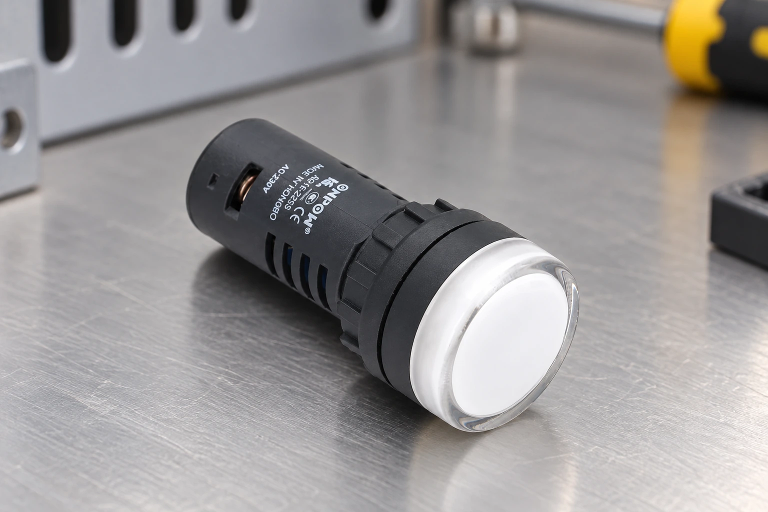
The images use a real ONPOW AD16-22D product reference. They illustrate the physical lamp and a panel location. They do not claim that the pictured variant has an internal flasher or a particular alarm rating. Ask ONPOW for the exact product data and tell the supplier whether the pattern will be generated externally.
For a supply-type comparison, read the 120V AC indicator-light guide and the indicator-light leakage-current guide for unwanted off-state glow. These issues should be separated from the alarm-pattern decision.
Verify the full sequence with representative users
Document the intended states before commissioning. Then test event arrival, acknowledgement, continuing condition, repeated condition, clearance, reset, and lamp test according to the authorized engineering plan. Compare the light behavior with the controller state and the operating instructions.
Check recognition from the intended work positions under relevant lighting conditions. Representative users should be able to explain what the signal means and what action to take. Do not make a new pattern a memory test for information that should be visible on the panel or display.
Electrical work and inspection must follow the applicable procedures with qualified personnel. United States workplaces can refer to 29 CFR 1910.333 for relevant electrical-work requirements. A flashing pattern is not proof that work near an energized panel is permitted.
Information to include in the purchase and design record
Specify supply and output interface, desired visible behavior, source of the signal, viewing distance, environment, mounting, labels, and acknowledgement sequence. Identify whether the lamp or the controller creates the pattern. Keep the exact product variant in the parts list.
Record the state matrix and commissioning results with the final control-program revision. If a later maintenance change replaces a steady lamp with an internally flashing one, review the resulting display behavior rather than assuming it is an improvement.
Vidéo éducative
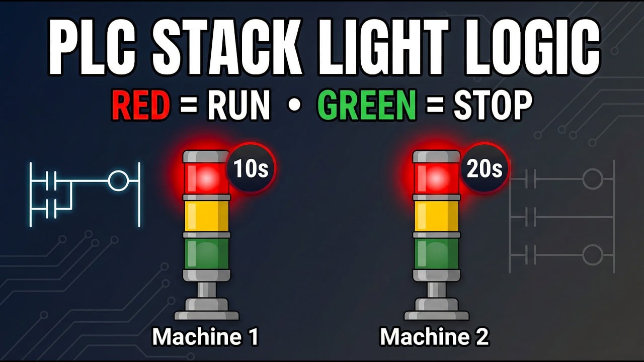
PLC Stack Light Logic by Instrumentation Tools. General educational background. Use the selected product drawing and the machine design for the actual circuit and installation. Watch on YouTube.
Foire aux questions
Is flashing always better for a fault indication?
No. It should serve a defined attention and response requirement. Excessive or inconsistent flashing can make the panel harder to interpret.
Can any steady indicator be made to flash by a PLC?
Only if the exact lamp and output interface support the circuit and operating conditions. Confirm supply, current, leakage, and switching behavior.
Should acknowledgement turn the light off?
The approved alarm strategy determines that behavior. Acknowledgement and clearing the underlying condition are separate events that may require different indications.
Does a lamp test prove all sensors are working?
No. It checks the functions included in that test circuit. It does not automatically validate upstream sensing or the complete machine-state logic.
What should an operator be able to identify?
The condition, its priority, the expected action, and whether acknowledgement or physical clearance is still required should be clear from the documented display strategy.



