

A bicolor indicator light gives a control panel two distinct visual states; a tricolor indicator can give it three. The extra color is useful only when the machine has a third condition that operators need to recognize quickly. It does not automatically mean that the device contains three independent circuits, that each color has a prescribed meaning, or that the third state is safer. The electrical behavior depends on the selected indicator and its control circuit, while the meaning of each color must be set by the machine design and applicable rules.
For compact panels, compare bicolor and tricolor lights by asking four questions: which operating states need a visible signal, how will the operator distinguish them, what outputs can the selected light accept, and how will the states be verified during commissioning? A color plan should be agreed before selecting the device. ONPOW’s GQ22 tri-color LED push-button example shows a round panel-mount button form, while the wider push-button range covers other operator-interface choices. Confirm exact wiring and ordering details from the current model documentation.
What bicolor and tricolor mean on a panel
The terms describe how many colors an operator can see from an indicator assembly. They do not, on their own, describe the LED package, the number of electrical inputs, or the control logic. A product may use separate LED elements, a multi-color emitter, or another internal arrangement. The front view cannot tell a buyer how the rear terminals are arranged.
The same caution applies to the word “state.” A red and green light might be used for two machine conditions, but the colors could also be used for two process phases or for a normal condition and an attention condition. A third color only adds information if the machine logic defines a separate, useful condition and the operator can act on it.
This is different from choosing a color based on a general color-meaning list. The existing industrial indicator-light color guide discusses color coding. This article focuses on the hardware and state mapping decision: whether one, two, or three visible colors are needed on a compact panel.
Bicolor versus tricolor at a glance
| Decision point | Bicolor indicator | Tricolor indicator |
|---|---|---|
| Visible conditions | Two planned conditions | Up to three planned conditions |
| Panel space | One light can represent two conditions | One light can represent three conditions |
| State mapping | Easier to keep a simple two-state legend | Needs a clear definition for the third state |
| Control interface | Confirm the required inputs and common terminal | Confirm how the product selects each color and whether combinations are allowed |
| Main design risk | Two colors may still be confused or read out of context | The third color may add complexity without adding useful information |
| Commissioning | Test both states, transitions, and power loss behavior | Test all three states, transitions, and any invalid or simultaneous command |
Use the table as a design checklist rather than a specification. Two products that look similar from the front may have different electrical arrangements. A catalog photo cannot replace the wiring diagram for the exact order code.
Start with the machine states, not the number of colors
Write down the conditions that must be visible before choosing a bicolor or tricolor part. For example, a machine may need to show “ready” and “running.” If those are the only operator-relevant conditions, a third color can create a question rather than answer one. If a third condition such as “attention required” is operationally distinct, a tricolor indicator may reduce the number of panel apertures.
For every proposed state, define:
- the machine condition that turns it on;
- which person needs to notice it and from where;
- the action the person should take;
- what the indicator does during transition, fault, startup, and loss of control power;
- whether the condition is also shown elsewhere, such as on a display or alarm.
The written definition should not say only “green is good” or “red is bad.” State names should describe the process, such as “cycle complete,” “manual mode selected,” or “temperature check required.” A color should support that message, not carry the entire message by itself.
Avoid assigning two different meanings to the same color on neighboring equipment if operators can see both panels at once. Also consider color-vision differences, glare, viewing angle, ambient illumination, and labels. A short text label or a distinctive position can reinforce the signal. The separate panel-indicator brightness guide covers visibility checks; brighter color alone does not fix an ambiguous state definition.

Confirm the electrical interface before ordering
The phrase “three-color indicator” does not tell you whether the device has three separate control inputs, a shared common, a polarity-sensitive supply, or an internal driver. Do not infer terminal count from the number of colors in a product photo. The exact schematic, voltage version, terminal identification, and permitted switching method must come from the supplier’s documentation for the chosen model.
Before releasing a bill of materials, ask the supplier to confirm:
- the exact part number and the colors available for that part;
- the rated supply and whether the indicator is AC, DC, or a specified version;
- the terminal diagram and whether the common is shared or isolated;
- whether two colors can be energized together, and what happens if they are;
- whether the light is intended for steady indication, flashing, or both;
- the required control output type and any load or polarity restrictions.
Then compare those details with the PLC output or relay contact in the machine. A controller output that can energize one channel is not automatically suitable for a multi-color assembly. The selection must include the output’s voltage, current, sourcing or sinking arrangement, off-state behavior, and any suppression or diagnostic circuit. If the output type is uncertain, resolve that with the controller manufacturer or a qualified controls engineer before wiring.
Use standards as a framework for indication design
IEC 60073 describes coding principles for indicators and actuators, and IEC 61310-1 addresses visual, acoustic, and tactile methods for safety-related information at the human-machine interface. These standards are a reason to treat indication as part of machine design, not as a decorative color choice. Their scope does not mean that a generic online color chart can replace the full standard, a risk assessment, or applicable machine requirements.
Document the meaning of the selected colors in the machine’s operating instructions and electrical drawings. Where a signal is safety-related, verify the full design against the machinery requirements that apply to the equipment and installation location. This article does not assign a universal meaning to red, green, blue, or any other color.
Decide whether one three-color button is better than several indicators
A single tricolor indicator can save panel area, but it concentrates multiple meanings in one point. Separate lights may be easier to read when conditions can occur at the same time. For example, if “machine running” and “service due” may both be true, a one-color-at-a-time device may hide one of the conditions unless the control logic provides another display.
Ask whether the states are mutually exclusive. If they are not, decide how priority is shown. A higher-priority alarm may need its own indicator or audible signal instead of replacing the normal status light. If operators must read the panel from a distance, separate position and a short label can be easier to interpret than a small light cycling through colors.
The physical layout also matters. Keep the indicator within the normal operator sightline, avoid placing it behind a door or handle, and check it at realistic viewing distances. Review the intended panel cutout, mounting depth, nut access, and neighboring components. A compact round illuminated push button can integrate indication with an operator control, but do not assume that the button’s electrical contacts and the lamp are the same circuit.

Commission every state and transition
Commissioning should confirm not only that each color can turn on, but that the machine reaches the intended color for each defined condition. Create a short test matrix with the process state, controller command, observed light, and expected operator response. Include startup, stop, fault, recovery, and power restoration.
Test one command at a time first. Then test invalid combinations, such as two color commands asserted together, if the hardware or control logic could permit them. Confirm whether the indicator goes dark, displays one priority color, or behaves in another documented way. Do not assume the result from the product family name.
Finally, ask an operator unfamiliar with the panel to interpret each indication using the label and instructions. If the operator has to guess, revise the state name, label, placement, or method of indication. A color-count decision is complete only when the meaning is clear in the real machine, not just in the drawing.
Foire aux questions
Is a tricolor indicator always better than a bicolor light?
No. Use a third color only when it communicates a distinct condition that operators need. If there are only two useful states, the added color may complicate drawings, control logic, and operator instructions without improving the interface.
Does a three-color light have three separate input wires?
Not necessarily. Internal design and terminal arrangement vary by product. Confirm the wiring diagram and exact model; never derive terminal count from a front-view image.
Can the three colors be used to mean the same thing on every machine?
Do not assume a universal mapping. Color coding should follow the applicable standards and the machine’s documented operating design. Check the full requirements for the equipment and market.
Can two colors be on at the same time?
Only the exact product documentation and the designed circuit can answer that. If simultaneous commands are possible, test the result and define an intentional priority or invalid-state response.
Should the indicator replace a text or alarm message?
Not by default. A light is useful for quick status recognition, but a safety-related or complex condition may need additional text, position, sound, or machine-specific instructions.
Vidéo éducative
The following PLC lesson shows how indicator outputs can represent defined machine states and why state logic should remain understandable. It is an educational example, not a universal color code or a wiring diagram for a particular ONPOW model.
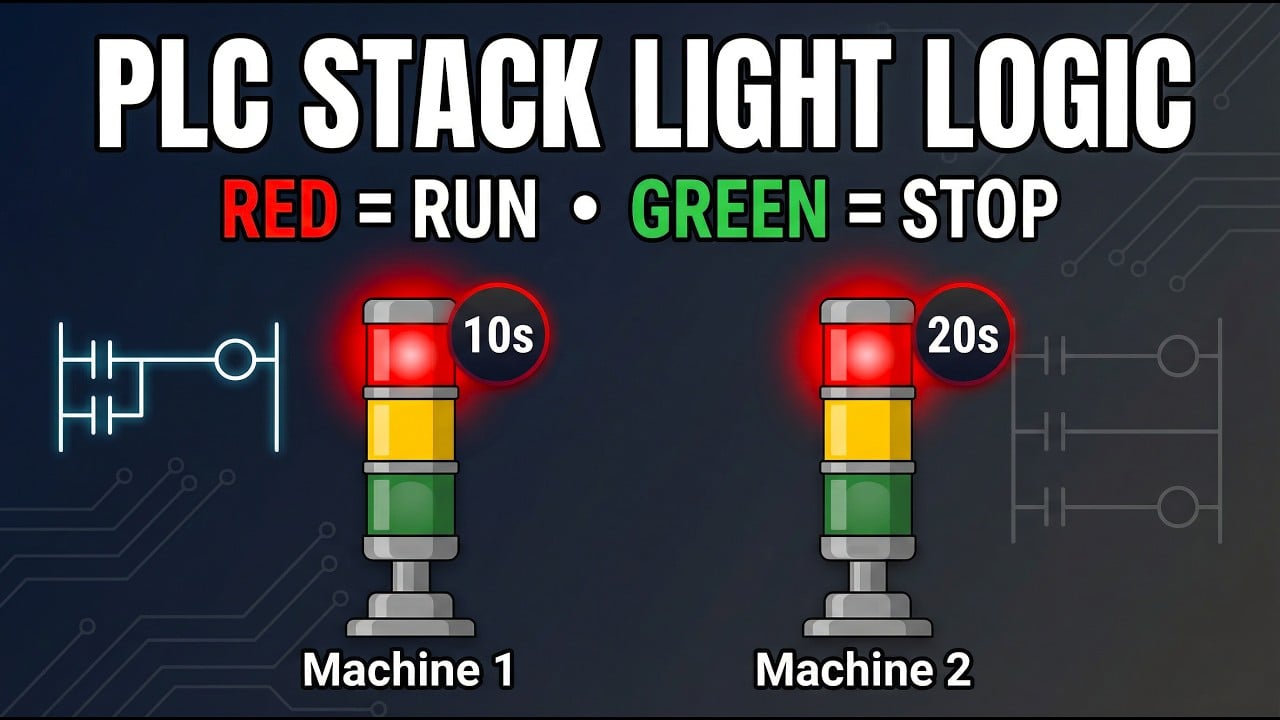
Watch the PLC indicator-state logic example.
Références
- IEC 60073: Coding principles for indicators and actuators
- IEC 61310-1: Safety-related indication, marking, and actuation
- National Instruments: Digital states, voltage levels, and logic families



