

A limit switch for a linear actuator should change its signal before the moving mechanism reaches a damaging position, allow the required stopping distance, and remain within the switch’s permitted travel. Start by identifying whether the actuator has internal limit control and what an external switch must add: process feedback, an adjustable stopping command, or a specified protective function. These are different requirements. Placement depends on target motion, operating point, controller delay, actuator coast, mechanical tolerances, and reset. Do not assume that an ordinary external micro switch can directly interrupt a motor or replace the actuator’s internal protection.
Define the external switch’s job first
A linear actuator may contain internal end-of-travel switching, electronic control, position feedback, or a combination. Read its actual documentation before adding an external device. An external switch can provide an earlier process signal or another defined control input, but its role must be stated in the equipment drawing.
Distinguish a positioning command from independent protective stopping. A process controller can use a limit signal to stop normal movement, while a separate protective function may require a different architecture and suitable devices. Calling a switch an end limit does not establish the reliability or fault response of the complete system.
The micro switch versus limit-switch guide explains the component and packaged-device distinction. For actuator interfaces, use limit-switch actuator types. This article focuses on the placement of an external device around linear motion.
Locate the target and its complete path
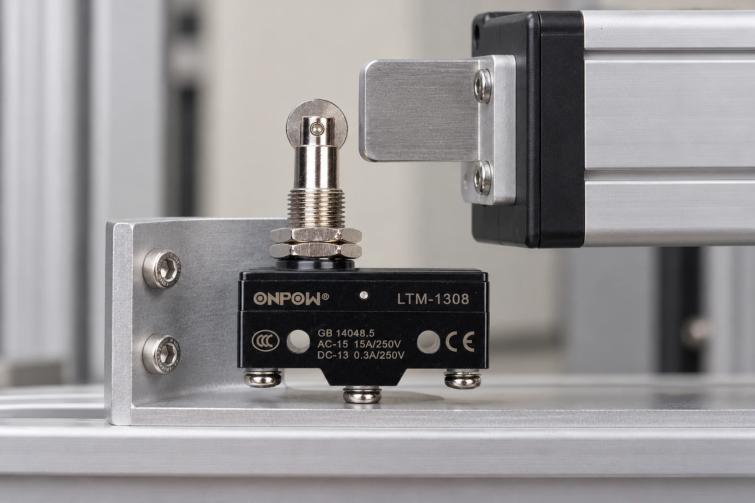
Choose a target surface or cam whose movement is well defined relative to the switch. Identify the approach direction, contact point, final operating position, and withdrawal path. The target should meet the selected actuator in its permitted direction, without side-loading a plunger or striking a lever outside its intended contact region.
Account for the carriage, brackets, guide clearance, actuator stroke tolerance, and any load-dependent deflection. The switch should be accessible for inspection without becoming vulnerable to normal material handling or maintenance activity. Protect the cable route from the moving rail and from any pinch point.
A target should remain operated for the intended dwell and then release reliably when the mechanism moves away. A switch mounted at a position the carriage merely brushes past can give a brief signal that the receiver may miss or misinterpret.
Set a trigger position with stopping margin
The contact’s operating point is not the same as the final machine position. The control signal must travel through the input, logic, output, driver, and mechanical system before motion ceases. The distance travelled during that response belongs in the placement review.
| Placement input | What to establish | Effect on the trigger position |
|---|---|---|
| Switch operating position | Exact actuator data and tolerance | Where the electrical transition begins |
| Input and logic delay | Verified receiver and program behavior | Motion continues before the stop command |
| Driver and actuator response | Actual equipment stopping behavior | Additional movement after the command |
| Mechanical variation | Bracket, target, guide, and stroke tolerances | Earliest and latest effective operation |
| Load and direction | Relevant motion conditions | Stopping distance can vary |
| Reset path | Target withdrawal and release position | Whether reverse movement restores the signal |
Use the equipment’s measured or declared response data. Do not use a generic switch article to assign a universal stopping distance.
Estimate a motion margin without treating it as a guarantee
For a simplified constant-speed interval, distance equals speed multiplied by elapsed time: d = v × t. If speed is in millimetres per second and time is in seconds, distance is in millimetres. This can estimate movement during a known electrical delay, but it does not include every braking, coast, or load effect.
As an illustrative calculation unrelated to an ONPOW rating, a carriage moving at 20mm/s travels 2mm during a 0.1s response interval. The installation still needs the measured stopping movement after the command and its tolerance margin. This example is not an allowable approach distance or a validated protective-stop calculation.
Use the least favorable relevant conditions in the review, including direction and load where they affect movement. Where the function is protective, the approved risk assessment and safety design determine the required method and margin. A nominal-speed calculation alone is insufficient.
Do not make the switch absorb the remaining stroke
The target must not compress the actuator beyond its permitted travel while the mechanism stops. An external mechanical stop or a suitable target profile should control excess movement where needed. The switch’s internal end position is not a general machine-stop rating.
A roller or cam arrangement can let the target move past an operating point while maintaining the intended signal, provided the geometry follows the manufacturer’s guidance. A direct plunger arrangement can require tighter control of continued movement. Compare the complete target path with the actuator’s operating and release positions.
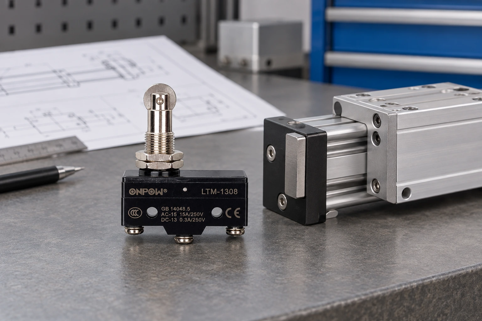
The roller-plunger limit-switch guide discusses the related interface. The ONPOW LTM-1308 product page supplies a real roller-plunger example, but its photograph does not specify allowable travel, target speed, or application stopping distance.
Separate feedback contacts from motor power
An external mechanical contact may be used with a controller input if its low-level switching capability and input interface are suitable. Direct interruption of an actuator motor is a different load. Starting, stalled, and inductive currents can exceed or stress a contact in ways not represented by nominal supply voltage.
Use the actuator and controller manufacturer’s approved circuit. Some systems use separate direction limits, internal switching, or specialized drive logic; others use external feedback through an input. Do not insert an arbitrary diode or reverse supply wiring based on a generic actuator diagram.
Confirm the exact contact arrangement, voltage and load category, wiring reference, and intended fault response. The limit-switch NO/NC wiring guide covers contact interpretation. IEC 60947-5-1 provides the standards scope for electromechanical control devices without approving a specific actuator circuit.
Verify the return movement and recovery sequence
A limit that remains operated after the mechanism moves away can prevent the next cycle or create an unexpected control sequence. Check that the target clears the switch far enough to cross its release point. Contact reset may occur at a different position from operation because of mechanical hysteresis.
The equipment must define how motion away from an active limit is permitted. A normal recovery command, a manual reset, and a maintenance override have different purposes and controls. Follow the actuator and machine design; do not bypass a limit to obtain reverse movement without an approved procedure.
Review power loss and restoration as part of the sequence. The drive may restart, remain inhibited, or require acknowledgement depending on the system. A switch’s NO or NC description does not establish the restart behavior of the controller.
Protect the mounting from movement and contamination
Use a stable bracket and the specified mounting method. Record the final adjustment reference and how it is secured. Fastener loosening, bracket flex, and cable pull can shift the trigger position even when the component still changes contact normally.
Consider vibration, process debris, coolant or cleaning exposure, temperature, and access. A switch body behind a guard is not necessarily protected from contamination. The actuator opening, terminals, and cable route all need review. Use the waterproof micro switch guide when sealing is required.
Inspect the target surface for wear or damage during maintenance. A changed cam edge can alter the trigger position without changing the switch. Keep the target and bracket references in the maintenance record with the component part number.
Commission at the actual motion conditions
Inspection and adjustment of installed machinery require qualified personnel and the relevant energy-control procedures. Stored mechanical or fluid energy can move an actuator even after a control stop. In United States workplaces, relevant requirements include 29 CFR 1910.147 and 29 CFR 1910.333.
Start with the approved isolated mechanical and contact inspection. During authorized operational commissioning, verify the trigger, receiver indication, stop command, final position, and release on return. Test the relevant directions and conditions defined by the engineering plan.
Record measured positions and any permitted stopping variation. Acceptance criteria should come from the machine design, not a universal article value. If the trigger margin is insufficient, correct the design or setting and repeat the affected checks before accepting production operation.
Supplier enquiry checklist
Provide actuator model, stroke, speed range, load conditions, controller or drive reference, target-motion sketch, mounting space, contact circuit, and environment. State whether the external switch is for ordinary feedback, process stopping, or a documented protective function.
Request the exact actuator option’s force, travel, contact ratings, installation instructions, and limitations. Ask the drive supplier how external limits should be interfaced. Keeping both sets of documentation together reduces the risk of selecting a mechanically suitable switch for an unsuitable electrical role.
Educational video
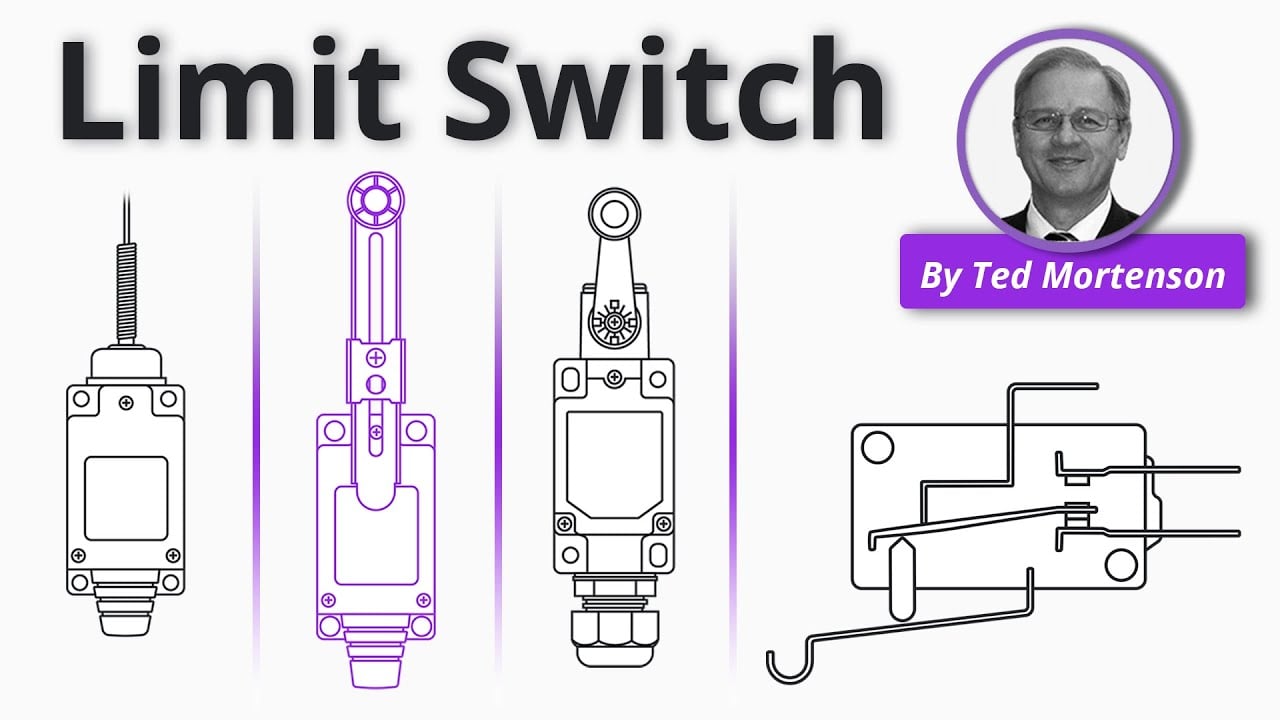
Limit Switch Explained | Working Principles by RealPars. General educational background. Use the selected product drawing and the machine design for the actual circuit and installation. Watch on YouTube.
Frequently asked questions
Does every linear actuator need an external limit switch?
No. Some have internal control suitable for the intended role. An external switch should have a defined additional purpose based on the actuator and machine documentation.
Can the switch be placed at the final desired stop position?
Not without evaluating response and stopping movement. The signal often needs to occur earlier so the complete system can stop within its permitted range.
Can a micro switch directly stop a DC actuator motor?
Only a documented contact rating and approved circuit can justify that use. A controller-input signal and motor interruption impose different electrical demands.
Why does the limit stay active after reversing?
The target may not have withdrawn past the release point, the actuator may bind, or the controller may retain a latched state. Review the physical and logical sequence separately.
What should be recorded after adjustment?
Record the switch and actuator models, bracket reference, trigger and final positions, release behavior, circuit drawing, test conditions, and acceptance results.



