

A capacitive touch switch can trigger when no operator intended a command if the sensor interprets noise, drift, a changing ground reference, moisture, or a nearby object as a touch. The visible symptom may be an unexpected machine input, an output that chatters, or a touch that becomes unreliable only after the enclosure is assembled. The correct fix is not to raise or lower a threshold at random. First separate the sensing electrode, controller, output, wiring, and machine input, then reproduce the fault under controlled conditions.
This guide is about diagnosing false triggering in capacitive touch systems. Actual limits and adjustment methods vary by product. Use the controller manufacturer’s guidance and the exact ONPOW model documentation; do not assume a metal touch switch exposes a user-adjustable sensitivity setting.
What counts as a false trigger
A false trigger is an output transition that does not correspond to the intended operator action. It can be a single unexpected event, repeated switching, an input that remains active after the user releases the surface, or a sensor that triggers when a nearby object approaches. These symptoms have different causes. A false touch at startup may point to baseline calibration or an enclosure change; a trigger synchronized with a motor or radio transmitter may point to interference or grounding; a persistent active state may involve contamination, an output fault, or application logic.
Start by recording what the machine actually observed. Compare the sensor’s reported touch state, controller output, PLC input, and machine response. If only the machine action is unexpected while the sensor output is correct, investigate downstream logic. If the sensor itself changes state, inspect the sensing environment and configuration. Never infer the cause solely from the front-panel light.
Common sources of false triggering
| Possible source | Clue to look for | Safe first check |
|---|---|---|
| Electrical noise | Events coincide with switching loads, relays, drives, or radio activity | Compare event logs with nearby equipment switching; inspect separation and routing against the controller guide |
| Ground or reference change | Behavior changes when a door, shield, or panel bond is connected | Review the approved bonding diagram and measure only under a safe, de-energized procedure |
| Baseline or calibration drift | False event appears after startup, temperature change, or slow environmental change | Check the documented startup/calibration sequence and stored settings |
| Moisture, residue, or cleaning film | Event follows cleaning or a wet/contaminated surface | Follow the product’s cleaning and environmental instructions; inspect only when safe |
| Mechanical assembly | The problem begins after fitting a cover, gasket, frame, or cable tie | Compare the exact production stack-up with the validated sample |
| Cable coupling or routing | Moving a cable changes response | Inspect sensor cable length, shield termination, separation, and routing per manufacturer instructions |
| Threshold too sensitive | Small disturbances trigger even on a stable bench | Verify the approved tuning range; change one documented setting at a time |
| PLC or output interface | Sensor state is stable but PLC input toggles | Check input type, output compatibility, common/reference, and the controller’s off-state behavior |
This is a troubleshooting map, not proof that any one mechanism is present. Keep a record of the original wiring, settings, product identity, and symptoms before changing the assembly.
Diagnose in a controlled order
First establish a safe machine state. If the interface can start motion, shut down or inhibit the equipment using its approved procedure. Do not open an energized cabinet or probe live conductors unless the task is specifically authorized and performed by qualified personnel with the required risk controls. A touch sensor is not an isolation device, and its output does not establish that a circuit is de-energized.
Next identify where the event originates. Use the machine’s diagnostic logs or a safe isolated test fixture to compare the sensor state with the controller output and downstream input. If the sensor changes while the PLC input stays stable, the logic or interface may be filtering the event. If the PLC input changes while the sensor output is stable, check the output/input electrical compatibility and wiring path. The exact terminal mapping and test points must come from the product and PLC drawings.
Reproduce the symptom. Note the date, startup state, operating load, door position, nearby equipment, cleaning history, operator approach, and whether bare fingers or gloves were used. Try one controlled condition at a time. Do not deliberately expose production equipment to a high-noise test or wet condition unless the test has been approved and the equipment is designed for it.
Then compare the installed build with the baseline test sample. Look for differences in panel thickness, paint, printed graphics, overlay, gasket, mounting hardware, rear clearance, cable length, shield routing, ground bond, and nearby metal. A successful bench test is weak evidence if the final panel assembly is materially different.
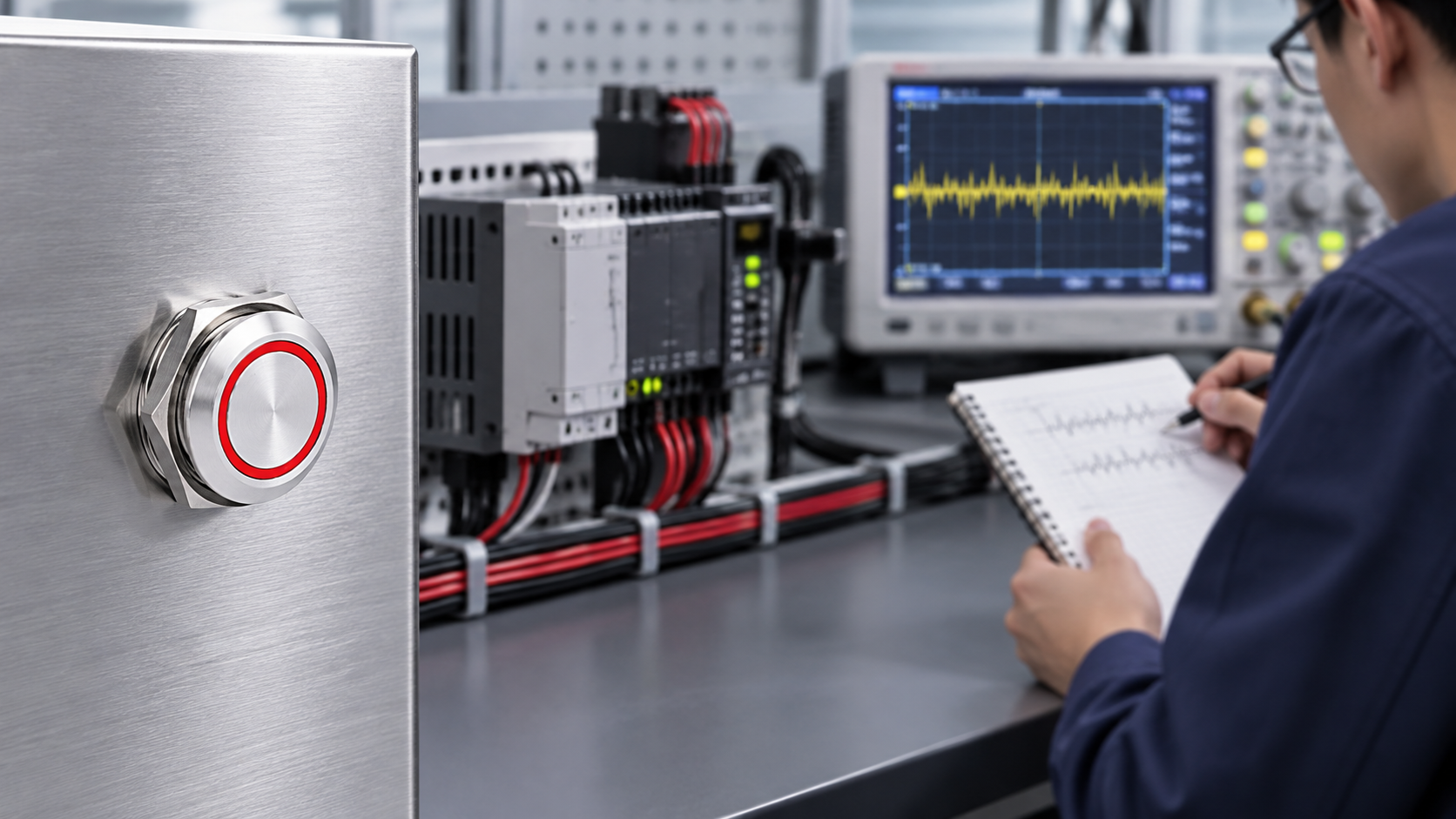
Grounding and reference: inspect before changing
“Ground” can refer to protective earth, chassis bonding, signal common, sensor reference, cable shield, or a controller’s internal reference. They are not interchangeable. A cable shield connected at the wrong point or a panel bond that changes between door-open and door-closed states may alter the electrical environment around a sensor. However, disconnecting protective earth or adding a new bond without an approved design can create a serious hazard.
Review the manufacturer’s recommended sensor reference and shield termination. Compare it with the equipment’s approved electrical drawings and applicable grounding rules. Keep protective bonding intact. If a test indicates that the panel reference is affecting sensing, involve the machine builder or a qualified controls/electrical engineer and document the corrective design before returning the machine to service.
Noise, filtering, and sensitivity adjustments
Noise immunity depends on the controller, electrode, sampling method, enclosure, cable, and nearby interference. Microchip publishes capacitive-touch robustness demonstrations for conducted and radiated noise; these show that immunity is something to design and test, not assume from the sensor category. The settings and mechanisms on a development board are not a substitute for the approved configuration of a production product.
If the exact controller permits adjustments, follow its application note. Change only one parameter at a time, keep the baseline configuration, and repeat both intended-touch and no-touch tests. A threshold that is too low may cause false triggers; a threshold that is too high may cause missed touches or force operators to press harder. Filtering may reduce brief noise but can add latency or mask a legitimate input. Hysteresis and debounce can stabilize a state, but they do not correct an unsuitable electrode or grounding arrangement.
Do not add a capacitor, resistor, shield plate, ferrite, or bypass path based only on a forum suggestion. An unapproved modification can alter sensor behavior, EMC performance, signal integrity, product warranty, or machine safety. Ask the device maker for a documented change path.
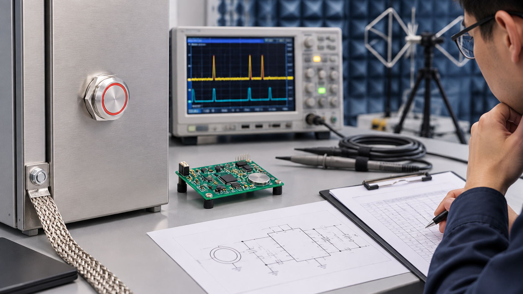
Prevent recurrence during design and replacement
Write a sensor-interface specification that names the product and controller, intended panel stack-up, mounting and bonding arrangement, output type, cable route, required bare-finger or glove operation, cleaning conditions, and machine response. Include defined behavior during startup, loss of supply, open sensor wiring, continuous touch, and controller reset where those conditions are applicable.
Validate the complete installed machine under representative switching conditions. Record intended-touch detection, no-touch stability, startup behavior, operator variation, and any approved environmental test. If changes are made to panel material, coatings, wiring, firmware, controller, grounding, or nearby equipment, determine whether a partial or full revalidation is necessary.
When replacing an existing switch, do not select only by cutout size or face appearance. Confirm output interface and sensing method. ONPOW’s touch switch vs push button guide explains the interface tradeoff; the broader capacitive and piezoelectric switch analysis compares technologies. For model-specific details, see the TS19A touch switch or TS22D touch switch product pages and confirm the exact drawing.
よくある質問
Why does a capacitive touch switch activate by itself?
Possible causes include electrical noise, a changing sensor reference, calibration drift, contamination, a changed panel stack-up, cable coupling, or downstream input compatibility. Compare the sensor output with the PLC state before changing anything.
Can a grounding change stop false triggers?
It may change the sensor’s electrical reference, but grounding must follow the machine’s approved design. Never remove protective bonding or add a ground connection by trial and error.
Should I reduce sensitivity to prevent false activation?
Only if the product supports a documented adjustment and the intended-touch detection remains reliable. Change one permitted setting at a time and test the complete machine after each change.
Can moisture make a touch sensor trigger?
Surface moisture or residue can affect some capacitive designs, but behavior depends on the product and environment. Follow the model’s cleaning and environmental instructions; do not infer an ingress rating from appearance.
Is a false-triggering touch switch safe to keep using?
If an unexpected touch can initiate hazardous motion, place the machine in the approved safe state and involve the responsible machine builder or qualified engineer. A sensor fault should not be treated as harmless without a risk review.
Educational videos
Microchip’s demonstrations show conducted and radiated noise testing of a specific capacitive-touch platform. They illustrate test methods, not a performance claim for ONPOW products.
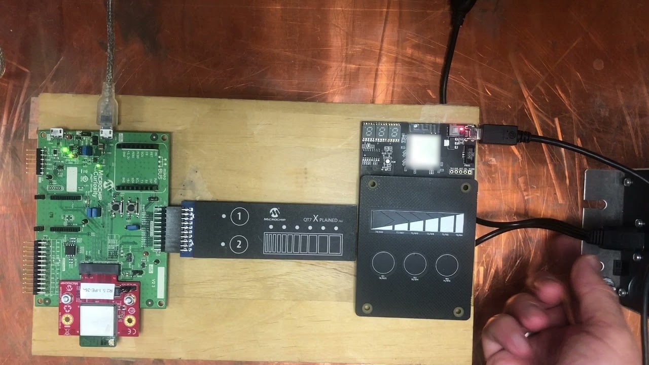
Watch Microchip’s conducted-noise test.
参考文献
- Microchip AN2934: Capacitive Touch Sensor Design Guide (PDF)
- Texas Instruments CapTIvate design guide
関連するONPOWガイド
For setup and product selection, compare capacitive touch switch circuit basics for metal panels そして touch sensitivity through glass and plastic. Both explain design boundaries; neither replaces the current model datasheet.



