

A capacitive touch switch can sometimes detect a finger through glass or plastic, but the result depends on the sensor design and the complete material stack. Overlay thickness, dielectric properties, air gaps, electrode size, grounding, sensor tuning, and the user all affect the available signal. “Capacitive” does not mean that every switch works through every cover. Texas Instruments’ TIDA-00343 reference design, for example, reports detection through a specific 10 mm glass window with a defined sensor/controller design; that is evidence for that design, not a specification for unrelated products.
This article explains how to evaluate touch through glass and plastic without assuming that an ONPOW metal touch switch supports a cover or a particular thickness. Treat the values in any vendor reference design as an example, and validate the exact sensor, overlay, enclosure, and environment you plan to use.
Why a capacitive sensor can respond through a cover
A capacitive sensing electrode establishes an electric field around its active area. A nearby finger changes the field and therefore the measured capacitance. A nonconductive cover such as glass, acrylic, or another plastic can sit between the electrode and the finger while still allowing a measurable change. The controller must distinguish that change from the sensor’s baseline and from noise.
The cover is part of the sensing system. A thicker or lower-permittivity material can reduce the change observed at the electrode. An air gap between the electrode and cover can also reduce coupling. A larger electrode may improve coupling in some designs but can increase parasitic capacitance, cross-talk, or sensitivity to nearby objects. The best geometry depends on the controller and the desired touch area, so there is no universal maximum thickness to quote for “capacitive touch.”
TI’s TIDA-00343 is a useful documented example: its design describes a variable air gap and detection through 10 mm glass under its specified implementation. Do not transfer that number to a different controller, panel, or switch. TI’s CapTIvate design guidance and Microchip’s capacitive touch design material likewise emphasize electrode layout, materials, spacing, and environmental effects as design variables.
Glass, acrylic, and other plastics are not interchangeable
| Overlay variable | What it can change | Practical evaluation |
|---|---|---|
| Material | Dielectric response and losses differ by material and formulation | Test the exact glass or polymer grade, not only a generic sample label |
| Thickness | More material between finger and electrode can reduce the detectable change | Test minimum, nominal, and maximum production thicknesses |
| Air gap | Adds separation between the electrode and overlay | Include gasket, adhesive, spacer, and assembly tolerance in the sample |
| Surface finish | Coating, printing, texture, or tint may change the sensor interface | Include ink, screen print, paint, and protective films in the final sample |
| Electrode size | Affects field shape and coupling area | Use the actual sensor geometry and intended touch target |
| Nearby conductors | Can distort or shield the field | Include grounded frames, screws, displays, and cable shields in the test |
| User and glove | Changes coupling and effective distance | Test representative users, bare fingers, and each required glove type |
The table is qualitative. It does not assign material constants or guarantee a sensing distance. A published material value is useful only when it matches the exact formulation, frequency, and measurement conditions of the design.
Keep overlay testing separate from product selection
An industrial touch product may have a flat metal face that itself forms the operator surface. That is physically different from a sensor mounted behind a glass or plastic window. Do not infer through-cover capability from a round metal front, a product category name, or a photograph. ONPOW’s TS19A product i TS22D product pages should be reviewed for the actual construction and ordering information. If the required interface needs sensing through an overlay, obtain written confirmation for the exact model and configuration before design release.
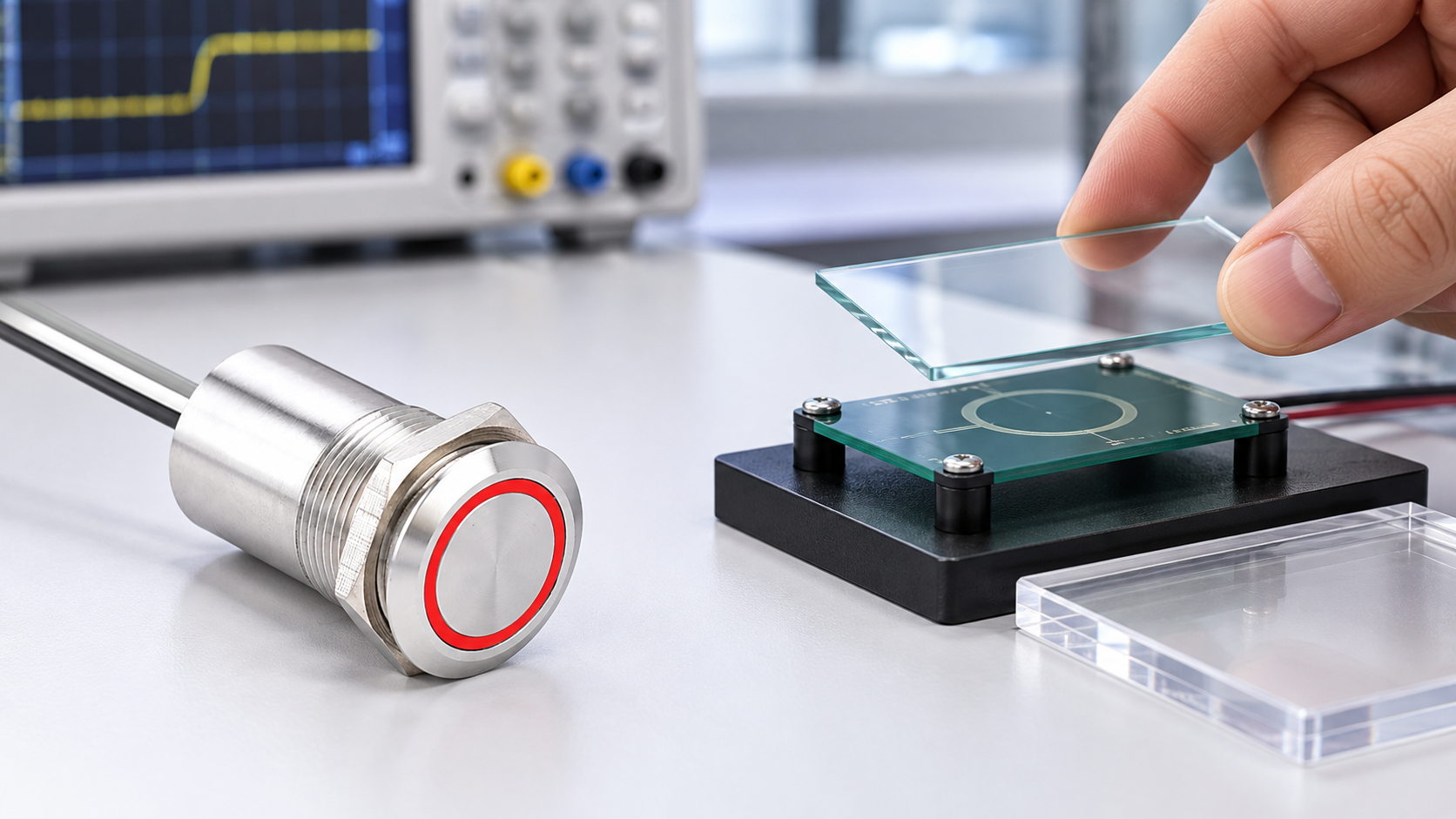
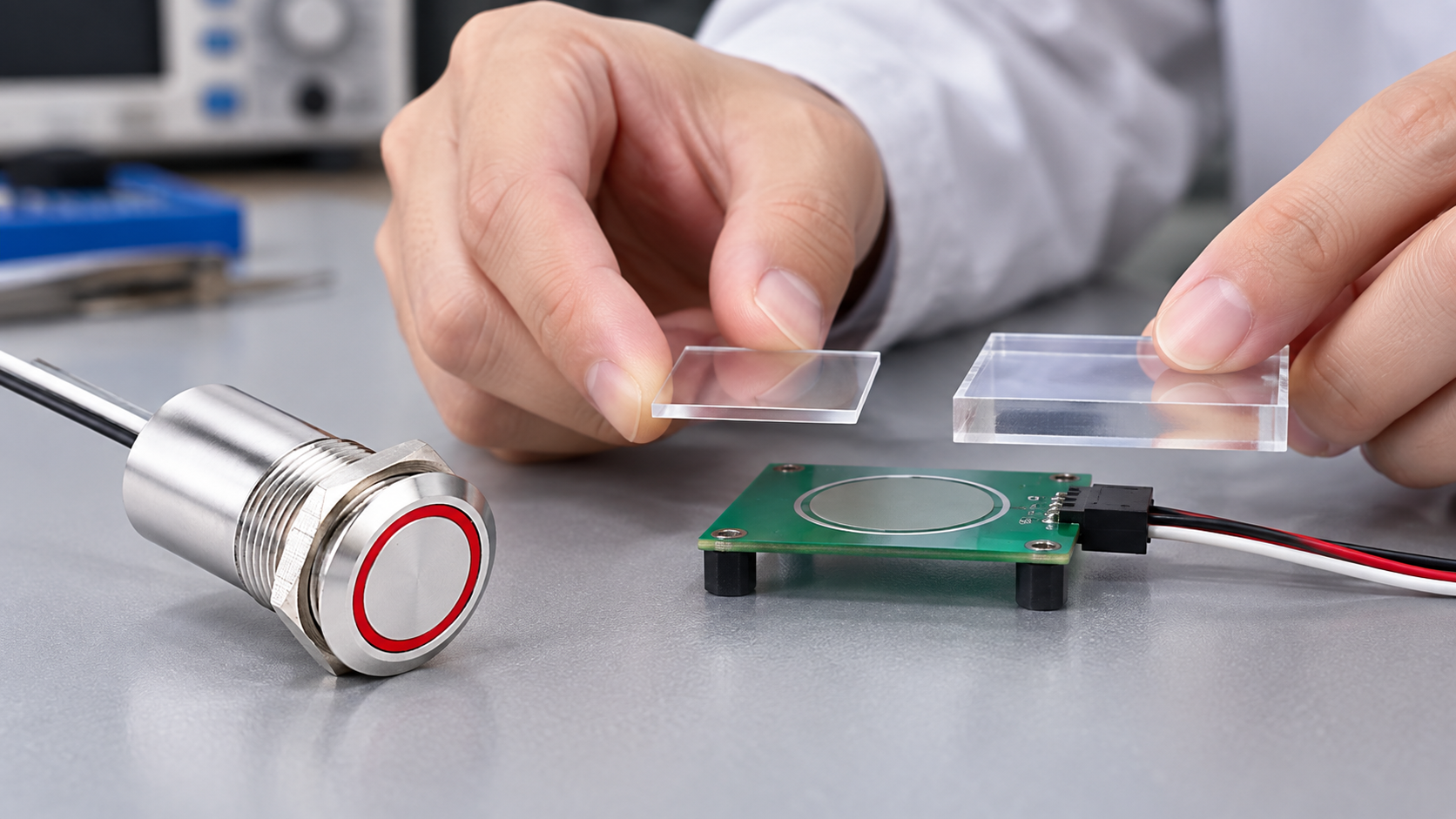
For a custom sensor, keep the sensing electrode, controller board, and overlay coupon distinct during the early test. Change one variable at a time: material, thickness, gap, electrode size, grounded frame, or user condition. Record the sensor configuration and firmware or controller settings so that a later test can be reproduced. After basic bench testing, move to the actual enclosure and nearby metalwork; a coupon on a laboratory table is not an assembled machine. For broader interface selection, see ONPOW’s metal-panel capacitive touch circuit guide i glove-operation validation guide.
Do not place an overlay over an existing touch switch as an informal experiment if that could damage the product seal, label, surface finish, or mounting. Use a sample assembly or an approved test fixture. An overlay can also alter cleaning, visibility, abrasion, ingress protection, and operator accessibility, which must be evaluated separately from sensing performance.
A repeatable overlay validation process
First define the required touch target and who will use it. Record the minimum reliable finger area, operating posture, approach direction, glove requirements, and whether the user can touch anywhere on the panel or only a marked area. A sensor that triggers on a large bare fingertip may fail with a small glove-covered fingertip.
Build a test stack that matches production: actual overlay lot and thickness, coating or printed graphics, adhesive, air gap, gasket, panel, frame, and mounting hardware. Include tolerance extremes and realistic temperature or humidity conditions if the product will encounter them. Do not use a thick transparent plate as a stand-in for a production window unless its material and dimensions are confirmed.
Establish a baseline and detection criterion using the controller’s approved process. Record the raw or reported signal when untouched, during a deliberate touch, during a near approach, and when a hand passes nearby. Check for false detection from vibration, a wet cleaning cloth if relevant, switching loads, cable movement, and adjacent controls. Repeat after power-up and after the enclosure is grounded and fully assembled.
If performance is marginal, do not simply increase sensitivity. Ask the controller manufacturer which electrode geometry, tuning, shielding, or filtering parameters are supported. A change can increase noise susceptibility or cause the touch to remain latched. Re-run the full test matrix after every change and document the revision that passed.
Information to confirm before specifying an overlay
When evaluating a commercial touch assembly, send the supplier the exact product code and a drawing or sample of the complete panel stack. Include overlay material and grade, minimum/nominal/maximum thickness, coatings and printing, adhesive, air gap, nearby grounded metal, cable length, controller model, operating supply, and required bare-finger or glove behavior. Ask whether that exact combination is supported, what test conditions were used, and whether the resulting output is a touch signal, relay contact, or another interface.
If the supplier cannot confirm the stack-up, use a non-production evaluation fixture and agree acceptance criteria before testing. Record successful touches and false activations, then repeat the test after the enclosure and electrical installation are complete. Do not convert a one-off demonstration into an environmental or safety claim.
Common mistakes when specifying touch through glass or plastic
The most common error is copying a maximum thickness from another vendor’s reference design. That result belongs to the specific controller, electrode, glass, air gap, firmware, and test procedure used in that project. It should not be presented as an industry-wide limit or as ONPOW product data.
Another error is testing only clear, uncoated glass and then releasing a tinted or printed production panel. Paint, conductive coatings, metal trim, adhesives, and decorative layers can change coupling. Likewise, the sample may be thin at its center but thicker at its edge, or production tolerances may enlarge an air gap.
Designers also sometimes treat a successful touch as proof that the interface is suitable for a machine command. Touch detection and the machine’s response are separate. The application still needs appropriate logic, feedback, fault behavior, access control, and safety validation. See ONPOW’s capacitive and piezoelectric switch comparison i touch switch versus push button guide for the broader interface decision.
Często zadawane pytania
Can capacitive touch work through glass?
Yes, in a design engineered and validated for the selected sensor and glass assembly. Performance depends on thickness, spacing, electrode geometry, controller settings, and the real enclosure; it is not guaranteed for every touch switch.
Can capacitive touch work through plastic?
It can, depending on the plastic formulation, thickness, coating, gap, sensor design, and controller. Test the exact production material and stack-up rather than relying on the generic word “plastic.”
Does a 10 mm example mean any sensor works through 10 mm glass?
No. TI reports that performance for its TIDA-00343 reference design and its defined configuration. It is an example, not a universal limit or ONPOW specification.
Does an ONPOW metal touch switch work behind a glass cover?
Do not assume so. Confirm the exact product construction and intended installation with its current documentation or ONPOW, then test the assembled panel if an overlay is required.
What should be tested before production?
Test the actual overlay material, thickness tolerance, finish, air gap, frame, grounding, sensor settings, bare-finger and required-glove use, nearby interference, startup, and final enclosure configuration.
Film edukacyjny
This Texas Instruments reference-design video demonstrates touch input through a defined glass window. Its performance belongs to that TI design and does not establish a thickness or through-cover rating for ONPOW products.

Watch the Texas Instruments touch-through-glass reference design.
Bibliografia
- Texas Instruments TIDA-00343: Low-Power Touch Through Glass Reference Design
- Texas Instruments CapTIvate capacitive-sensing design guide
- Microchip AN2934: Capacitive Touch Sensor Design Guide (PDF)
Related ONPOW products and guides
Review the TS19A touch switch i TS22D touch switch pages for product-specific construction. For selection context, read Touch Switch vs Push Button and ONPOW’s capacitive and piezoelectric switch comparison.



