

A modular tower light should have enough tiers to show the machine states an operator must distinguish—and no more than the process can clearly define. Choose the tier count from a written state list, the required operator actions, available control outputs, viewing conditions, and the exact product configuration. A five-tier tower is not automatically better than a three-tier unit: unused colors add wiring and interpretation work, while too few tiers can hide meaningful states.
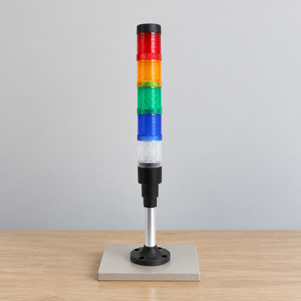
This is a planning guide, not a universal color code. ONPOW’s multilevel warning-light range includes products with different layer counts and configurations. For a five-tier model example, see the HBJD-55A/D/5/RYGBW/A product page; confirm the current ordering code, available modules, electrical details, and mounting options with the product documentation before specifying it.
Start with machine states, not the tower catalog
Write down every condition that must be visible from the operator’s normal position. Name conditions in process language—such as “cycle running,” “material required,” or “fault acknowledged”—instead of beginning with “red,” “amber,” or “green.” For each condition, record who needs to notice it and what response is expected. If two conditions require the same response and do not need to be distinguished, they may not need separate tiers.
A tower can display one state at a time, multiple simultaneous states, or a sequence, depending on the model and control design. Decide which behavior the machine needs. A stacked state display can help when several conditions may be true together; a mutually exclusive indication may need fewer outputs. Do not assume the tower internally arbitrates simultaneous commands or supplies a particular flash pattern unless the selected model’s documentation says so.
A practical tier-count decision table
| Design question | What to define | How it affects tier count |
|---|---|---|
| Distinct operator states | Conditions that require different recognition or action | Count only states that must remain visually distinct at the same time |
| Simultaneous conditions | Whether machine states overlap or replace one another | Overlapping states may need separate lit tiers or another display strategy |
| Control outputs | Available PLC outputs, relay contacts, or approved interface channels | Confirm that the chosen product exposes the required control inputs |
| Viewing distance | Operator location, angle, obstructions, and ambient light | A larger stack is not a substitute for a visible, well-positioned signal |
| State ownership | Which equipment or process unit the tower represents | One tower should not ambiguously combine unrelated machines |
| Future change | Approved expansion needs and likely process changes | Add a spare tier only when a defined future state justifies its wiring and legend |
The table is a design prompt, not a product specification. Exact tier availability, color options, voltage, sounder, and input arrangement depend on the selected model. The ONPOW product range should be checked alongside its current drawings and model details.
Map every tier to a defined condition
After estimating how many states matter, make a state-to-tier matrix. Record the machine condition, the tier or combination that represents it, the operator response, and the control output. Include startup, stopped, fault, reset, and loss-of-power behavior. This catches undefined colors and contradictory combinations before parts are ordered.
| Example state | Operator message | Design check |
|---|---|---|
| Idle or ready | Machine is available but not cycling | Decide whether this state needs a continuously visible tier or is the default with all tiers off |
| Running | The automatic or manual cycle is active | Confirm the signal starts and ends at the correct process transitions |
| Attention required | An operator action or replenishment is needed | Define the action and whether it can coexist with “running” |
| Fault | A defined fault state needs attention | Coordinate the tower with the machine alarm strategy and fault display |
| Service or special mode | A separate mode must be visible to the people nearby | Decide if this deserves a tier, a keyed control/label, or another interface |
These are example labels only; they do not assign a standard meaning to any color. IEC 60073 provides coding principles for indicators and actuators, while IEC 61310-1 addresses visual, acoustic, and tactile signals for machinery. Consult the applicable standard and machine requirements for the actual application. ONPOW’s tower-light color guide discusses color meaning; this article focuses on the number of signals and the design decision, not a replacement color code.
Decide whether states are exclusive or can overlap
The most important count question is often not “How many states exist?” but “How many must be seen at once?” If a machine can only be idle, running, or in fault—one state at a time—a defined selection scheme may use fewer independently illuminated tiers. If “running” and “material low” can occur together, a design that displays only the highest-priority condition may hide useful information. A stack that allows multiple modules to remain lit may make those conditions visible, but only if the product and control system support that behavior.
Write down the priority rule when states conflict. For example, a fault might override normal-running indication, or an attention request may remain visible while the machine continues to run. Confirm how the electrical outputs implement that rule and how the operator understands it. The visual display must agree with the HMI, alarm logic, and operating procedure; otherwise adding tiers can make the panel less clear rather than more informative.
Check product configuration and output capacity
The number of colored lenses visible in a photograph does not prove how many separate input wires or independent channels the product provides. Verify the exact part number, supply version, included modules, wiring diagram, and any sound or flashing function. The ONPOW HBJD-55 family product page illustrates a multilevel tower family, but the selected variant and its diagram govern the actual connection.
Compare the wiring diagram with the control hardware. Count the outputs required for the selected operating mode, check the controller’s sourcing or sinking arrangement, supply voltage, channel and group limits, and decide whether an approved relay or driver is needed. Do not assume a controller output can drive every tier directly. Do not infer electrical assignments from insulation colors in an image. If the selected stack includes a sounder, separately define its audience and alarm pattern; ONPOW’s industrial buzzer selection guide covers those considerations.
Consider visibility and operator context
Tier count does not determine whether the tower can be recognized. Select a mounting position where the intended people can see it without obstruction, including from normal working positions. Consider viewing distance, angle, ambient light, reflections, machine guarding, nearby equipment, and whether more than one tower may be visible at once. A signal that can only be seen from one aisle may not serve operators on the other side.
Use labels, an HMI message, or written operating instructions where color alone is not enough. Keep the tower associated with a specific machine or zone, and make the state legend consistent across similar equipment. If color discrimination is a concern, include position, text, sound, or another appropriate cue as part of the design. A larger stack does not fix a poor location or an ambiguous legend.
Avoid adding tiers “just in case”
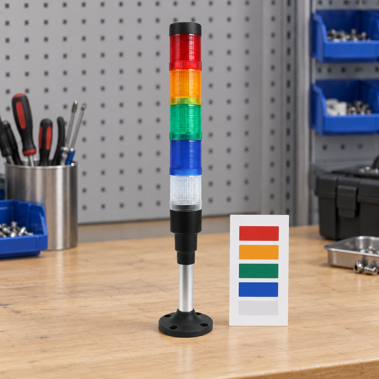
A spare tier can be useful when an approved expansion is already defined. Otherwise it can create an unused signal, an unwired input, or a future color convention that no one documents. More tiers also mean more choices to name, wire, program, test, explain, and maintain. Add one only when the state list or approved expansion plan identifies what it will represent and who will respond to it.
If a product has more physical modules than the first application needs, mark unused channels in the drawing and commissioning record. Make sure unassigned modules cannot turn on unexpectedly because of floating inputs or an incorrect common connection. If a later process change uses the spare tier, update the PLC logic, wiring diagram, operator legend, maintenance documentation, and training together.
Commission the full state matrix
Before handover, test every defined state and transition at the machine. Verify that each commanded condition illuminates the intended module, that simultaneous conditions behave as designed, and that startup, reset, power restoration, and communication or output faults produce understandable indications. Test from the operator’s actual viewing positions and confirm the legend matches the observed signal.
Keep the test record tied to the full product code and wiring drawing. The IEC 61310-1 scope provides a framework for considering visual and other signals at the machine interface; the machine’s applicable standards, risk assessment, and approved procedures determine the required verification. A stack-light test is not, by itself, proof that a safety function is adequate.
Educational video
This ACC Automation tutorial shows a generic stack-light and PLC wiring example. It can help visualize a controls connection, but it does not determine the correct tier count or replace ONPOW’s exact wiring diagram.
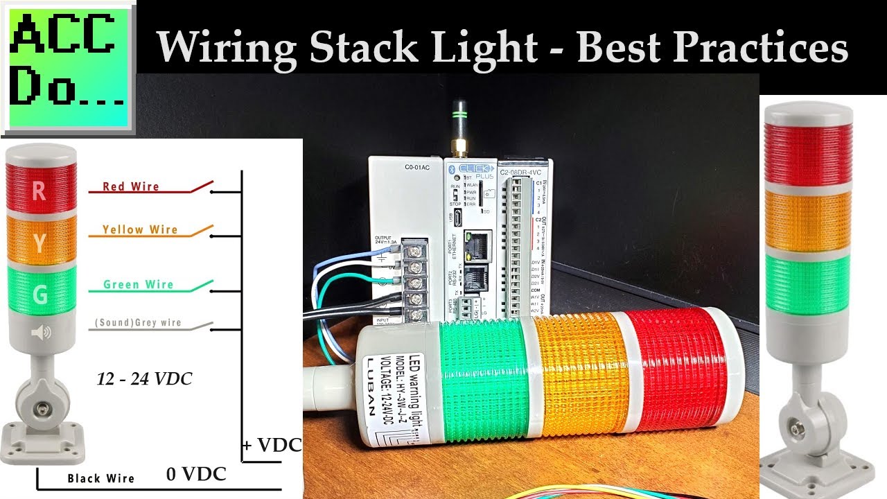
Watch the generic stack-light and PLC wiring tutorial.
Frequently asked questions
How many tiers should an industrial tower light have?
Choose enough tiers for machine states that operators must distinguish, especially when conditions can occur together. Confirm the product’s actual input arrangement and output capacity before setting the count.
Does every tier need its own PLC output?
Not necessarily. The required outputs depend on the selected tower, its internal functions, and the desired control behavior. Use the exact wiring diagram and controller documentation rather than assuming one output per visible lens.
Should I install an extra tier for future use?
Only when an approved future state is defined. Document the unused input and ensure it cannot activate unintentionally; update the control logic and operator legend when the tier is commissioned.
Do tower-light colors have universal meanings?
Do not assume that a generic online list defines the correct meaning for every machine. Follow applicable standards and machine requirements, and document a consistent state legend for the equipment and its operators.
Can more tiers make a machine easier to understand?
They can show more distinct conditions if each has a clear meaning and the hardware can display them as intended. Unused or conflicting signals add complexity, so validate the state matrix with operators before finalizing the design.
References
- IEC 60073: Basic and safety principles for man-machine interface, marking and identification — Coding principles for indicators and actuators
- IEC 61310-1: Safety of machinery — Indication, marking and actuation — Part 1: Requirements for visual, acoustic and tactile signals
- National Instruments: Choosing an industrial digital I/O module



