

When a stack light shows the wrong tier, stays dark or has an unexpected signal, trace the machine command, controller output, supply, common connection and exact tower model before replacing the unit. The same symptom can come from program logic, an output channel, a loose connection or a mismatched lamp configuration. This guide covers industrial machine signal towers; it is not a universal wiring diagram or permission to probe an energized cabinet.
Start with the selected model’s diagram. ONPOW’s HBJD-40M multilevel warning light is one product example, while the multilevel warning-light range includes different layer, voltage and sound configurations. Check the complete model code and its own drawings before using a manual for a similar-looking device.
Match the symptom to a fault path
Record which tower sections illuminate, whether the machine is requesting a signal, and whether the fault is constant or intermittent. Do not use lens color by itself to guess the electrical fault; use the machine’s legend and the selected product’s terminal diagram.
| Observed symptom | First evidence to check | Possible areas to investigate |
|---|---|---|
| All tiers are dark | The machine condition, PLC output state and documented supply to the tower | Logic or interlock state, output module, supply, common connection, fuse or disconnect |
| One tier does not light | The command for that tier, channel status and model-specific connection | Output channel, terminal, cable, module or a product configuration mismatch |
| Wrong tier or color appears | The programmed output-to-tier mapping and the written signal legend | PLC mapping, terminal assignment, model layer order or commissioning change |
| Signal flickers or changes unexpectedly | When the event occurs, controller diagnostics and the actual output state | Loose connection, output/load compatibility, unstable supply or a logic transition |
| The buzzer is silent but lights work | Whether the selected model includes a buzzer and how its sound function is commanded | Sound option, separate output/common, mute logic or buzzer condition |
This table helps isolate the next check; it is not a pinout. The actual wiring and permitted measurements depend on the model, control voltage and machine design.
Confirm the part and the signal condition
Read the order code from the installed unit or original bill of materials. Confirm layer count, lens arrangement, mounting style, supply version and whether sound is included. Similar-looking HBJD models may not share the same connections or common conductors. The manufacturer’s current drawing for that exact part takes precedence over a picture, a wire color remembered from another installation or an online discussion.
Next, define what the machine should be showing. Is it in automatic run, waiting for material, faulted, in a maintenance mode, or intentionally muted? Check the PLC/HMI logic or machine event record using the documented diagnostic process. A signal can be electrically healthy but appear “wrong” if the control sequence maps a condition to a different output than the operator legend expects.

Trace the output before changing wiring
Observe the controller output state using the approved diagnostic tool. Compare it with the machine’s electrical drawing and the exact tower diagram. A status LED on an output module is useful evidence, but it does not prove that the required voltage and current reach the tower’s own terminals.
Check whether the output is sourcing or sinking current, the supply reference, channel or group limits, and any output protection or leakage current described by the controller manufacturer. National Instruments’ industrial digital I/O connection guide explains these output arrangements for its own hardware; the installed PLC manual governs your actual connection. Do not translate a generic sourcing/sinking explanation into a wire color or a universal connection rule.
ONPOW’s HBJD-40/40A signal-tower wiring guide demonstrates why model-specific manuals matter: it shows differences between the listed models and includes a caution about the common wires for those versions. Those lead assignments are not a wiring diagram for HBJD-40M or another tower model. Use the manufacturer drawing that matches the installed product.
Inspect only after the machine is safely isolated
If the documented output and intended state agree but the light still behaves incorrectly, follow the site’s safe-isolation and lockout procedure before opening the cabinet or touching terminals. A qualified person can verify the de-energized condition, inspect for a loose terminal or damaged cable and check the model, module seating and mounting. Never use a continuity setting on a live circuit or bypass an interlock to see whether the tower turns on.
Where a powered test is necessary, use the machine’s approved commissioning method, suitable rated equipment and qualified personnel. Compare measurements with the exact product and controller ratings. Do not connect an arbitrary bench supply, bridge output channels or join commons because another model used a similar color arrangement.

Compare the requested signal with the visible result
Follow one machine condition end to end. Write down the state that should be shown, the controller condition that represents it, the output channel assigned to that state and the physical tier that should illuminate. Check the sequence in the approved ladder or control documentation. If the program never requests the output, changing the tower will not correct the cause. If the requested output is active but the corresponding tier is dark, the issue may be in the output interface, field connection, common path or lamp module.
When the tower shows the wrong tier, compare the complete model code and lens order with the machine legend. Do not assume that a red, amber or green lead has the same meaning on every supplier’s device. For the selected ONPOW version, use the drawing for that exact model and order of layers. A mismatch introduced by a replacement part can look like a programming error even if the controller logic has not changed.
For a fault that appears only during vibration, a particular cycle or a cabinet-door movement, record the machine state and the time of occurrence before making changes. That evidence can help a qualified technician distinguish an intermittent connection from a control-sequence transition. Never leave a disconnected or bypassed signal in service as a workaround; restore the approved configuration and verify the relevant machine states.
Use a repeatable commissioning sequence
After correcting a wiring, configuration or product fault, test one commanded output at a time. Verify each physical tier, then test intended combinations, transitions, startup, reset and loss-of-supply behavior. Confirm any buzzer separately and make sure its function matches the selected model. Reconcile the result with the HMI message and the posted operator legend.
Record the full part number, drawing revision, controller channel, observed symptom, evidence and change made. This keeps intermittent faults from being “fixed” without knowing what changed and helps prevent the same condition from being wired differently on a second machine. IEC 60204-1 covers the broader electrical equipment of machinery; the standard does not supply a universal tower-light pinout or replace the machine’s risk assessment.
Common stack-light troubleshooting mistakes
Replacing the complete tower before checking the command. Verify the machine state and output indication first; otherwise the new device may show the same fault.
Using the wrong model drawing. A nearby model can have a different voltage, layer order, sound option or common arrangement.
Assuming the PLC output LED proves the tower has power. The supply, common, output topology and field wiring still need to match the approved design.
Applying a wire-color convention from memory. Wire colors and commons vary by product and model. Follow the exact diagram.
Mixing light and buzzer commons without checking the manual. Some models use separate connections for light and sound modes. Do not combine conductors unless the specific manufacturer documentation shows that arrangement.
Treating the tower as a safety function on its own. A signal light indicates a defined condition. It does not by itself ensure a person recognizes, understands or responds to a hazard.
Educational video
This PLC tutorial from Bob Teaches Tech demonstrates a timer sequence that drives a three-color stack light and shows how to troubleshoot the sequence logic. It is a generic Mitsubishi-style example, not an ONPOW wiring diagram or model-specific terminal guide.
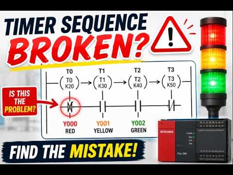
Watch the stack-light PLC sequence troubleshooting example.
Frequently asked questions
Why is my stack light dark when the PLC output appears to be on?
The output indicator is only one check. Verify the exact model supply, common, output topology, field wiring, channel limits and the voltage at the tower using an approved method and qualified personnel.
Why does the wrong color light on a tower?
Compare the machine condition, PLC output mapping, model-specific terminal diagram and lens order. A program change or wiring mismatch can make the visible tier disagree with the operator legend.
Can I use one tower-light wiring diagram for all models in a series?
No. A series can include different layer counts, voltages, mounting styles and sound options. Match the diagram to the full installed order code.
What should I check when only the buzzer is not working?
Confirm that the selected tower includes a sound function, then check its documented output, common and mute logic. The separate industrial buzzer troubleshooting guide covers the buzzer-specific diagnostic path.
Is a stack light a safety-rated warning device by itself?
Do not assume so. Follow the machine’s risk assessment, applicable requirements and safety design. A visible status light alone does not prove that a required safety function is achieved.
References
- IEC 60204-1 — Safety of machinery: electrical equipment of machines
- National Instruments: Industrial digital I/O signal connections
- ONPOW HBJD-40/40A signal-tower wiring guide



