

An electromechanical relay wiring diagram normally separates two paths: the coil circuit that moves the relay, and the contact circuit that switches the load. Start by finding the diagram printed on the exact relay or its datasheet, then identify the coil, common (COM), normally open (NO), and normally closed (NC) terminals. The labels and pin numbers are not universal. A drawing for a five-pin automotive relay, a plug-in control relay, and a safety relay can look similar while describing different devices.
The safe reading sequence is: identify the relay’s de-energized state, trace the coil supply and return, choose the required contact state, trace the load path, and verify the finished circuit with the equipment isolated. The example below explains generic contact logic only; it is not a pinout or installation diagram for every model. ONPOW’s ORJ2SL relay product page and industrial relay range are starting points for model-specific documentation. For broader device selection, see the existing electromechanical relay selection guide.
Read the relay’s own diagram first
Before connecting any wire, locate the schematic for the exact part number and coil version. Depending on the product, it may be printed on the side of the housing, included on a plug-in relay’s case, or supplied as a separate datasheet. Photographing or recording that diagram with the work order helps prevent a later replacement relay from being wired by visual guesswork.
Look for two groups of symbols. A coil is usually shown separately from one or more contact sets. A dotted or mechanical link may show which contacts move together when the coil operates. In a simple monostable relay, the contact diagram is normally drawn with the coil de-energized. A latching relay, a polarity-sensitive DC coil, a suppression diode, or an electronic interface module can require different treatment, so read the notes beside the manufacturer’s symbol.
Do not start with a remembered pin number. Numbers such as 30, 85, 86, 87, and 87a are associated with certain automotive relay conventions, while industrial relays may use other terminal numbering. Some relay bases show numbers on the socket rather than the relay. Even two products with the same number of blades can arrange them differently. Use the terminal designations and drawing printed for the specific model.
Separate the coil path from the switched path
The coil path is the control side. It energizes the relay’s magnetic mechanism, but it is not automatically the same voltage or circuit as the switched load. The load path passes through the relay contacts and is normally drawn separately. Keeping the two paths visually distinct makes it easier to review which circuit is controlling the relay and which circuit is being switched.
In a generic control example, the coil path can be represented as a suitable control output and supply connected across the two coil terminals. The contact path can be represented as the load supply passing through a protective device, into COM, out through the selected NO or NC contact, and onward to the load return. That description is a way to read a schematic, not a universal wire-color or pin-number instruction. Actual grounding, isolation, protective bonding, fusing, and conductor sizing depend on the machine design and applicable electrical requirements.
Check the coil marking before applying power. Confirm AC or DC, rated voltage, polarity if specified, and whether a diode, LED, or other suppression component is built in. A suppression diode can make a DC coil polarity-sensitive. An external suppression component may change release time or the voltage seen by the driver. Follow the relay and controller documentation rather than assuming every coil behaves the same way.
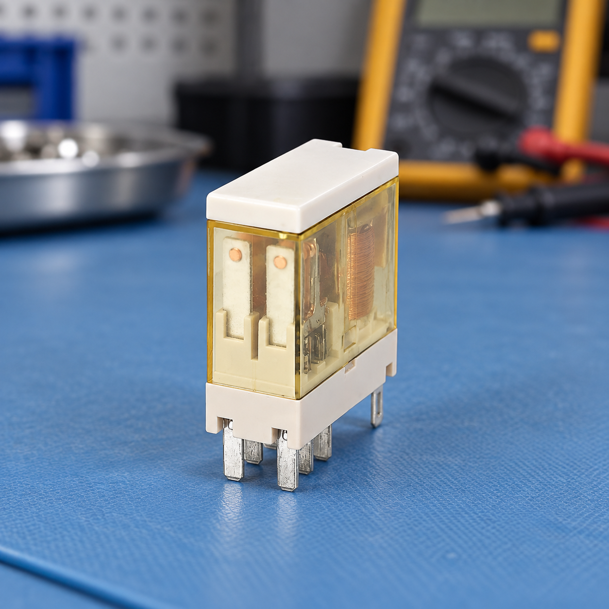
Understand COM, NO, and NC in the de-energized state
For a standard non-latching changeover relay, the NO and NC names describe the contact state while the coil is not energized. COM is the moving or common side of that contact set. With the coil released, COM is connected to NC; when the coil operates, COM transfers to NO. A relay that has only an NO contact or only an NC contact may not expose all three terminals.
Use this table to interpret common drawing labels; do not use it to infer physical pin positions:
| Diagram label | Typical state with coil de-energized | Typical state with coil energized | O que verificar |
|---|---|---|---|
| Coil terminals | No magnetic actuation | Coil is actuated when its specified supply is applied | Exact coil voltage, AC/DC type, polarity, and any suppression component |
| COM | Connected to the selected resting contact | Transfers to the alternate contact on a basic changeover relay | The common terminal for the exact contact set shown in the datasheet |
| NC | Closed to COM in the normal, de-energized state | Opens from COM when the relay operates | Whether “normal” in the drawing means coil de-energized, and whether the relay is latching |
| NO | Open from COM in the normal, de-energized state | Closes to COM when the relay operates | Contact rating for the actual load and switching duty |
The words “normally open” and “normally closed” do not mean that the terminal is inherently safer or more reliable. They describe a contact’s state in the defined normal condition. For a comparison of these contact conventions, read the NO versus NC switch guide.
Trace a generic load circuit one node at a time
Once the contact set is identified, follow one continuous path on the diagram. For a load that should be off while the relay is released and on when the coil operates, the logical path is usually source → circuit protection → COM → NO → load → return. If the load should be on in the relay’s released state, a designer may use COM and NC instead. This does not make a circuit fail-safe by itself: a welded contact, broken wire, lost supply, or failed controller can produce other outcomes.
In a working drawing, show the control supply, coil, contact set, load supply, protection, and return in a way that makes their circuit boundaries clear. Where the control circuit and load circuit have different supplies, don’t connect their returns together unless the system design explicitly requires it. A relay contact may provide separation, but the complete panel still has grounding, insulation, overcurrent, and segregation requirements.
If the relay switches a motor, heater, lamp bank, solenoid, or other demanding load, check the rating for that load category and its inrush or inductive behavior. A contact’s headline current is not sufficient evidence that it can switch every load at that current. For motor power or other high-energy circuits, the correct device may be a contactor or a purpose-designed switching assembly, not a small interface relay. Have a qualified controls or electrical professional verify the design before energizing it.
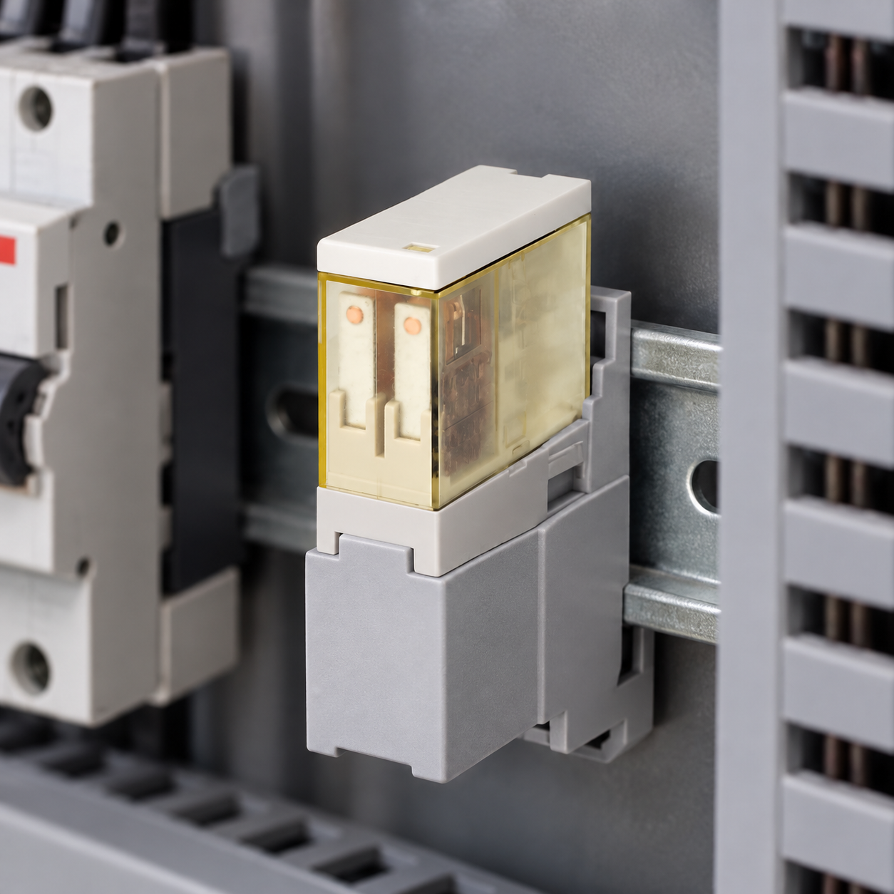
Verify terminals before connecting the load
With the circuit de-energized and the relay removed if the design allows, use the manufacturer’s diagram and a suitable continuity check to confirm which contacts are open or closed in the released state. A continuity check is a verification step, not a substitute for the diagram: parallel paths elsewhere in the panel can affect a reading. If a measurement is ambiguous, isolate the relevant conductors or ask a qualified technician to review the circuit.
For the coil, use the test method and limits specified by the manufacturer. Do not apply an arbitrary voltage simply because the relay looks familiar. Do not use a multimeter resistance function on an energized circuit. Before a powered functional test, confirm that the load is safe to operate, covers are in place, and the control sequence will not unexpectedly start machinery.
Record the final terminal mapping in the panel drawing and label the circuit at both ends where required by the project. If the relay is replaced later, the person doing the work should be able to identify the coil supply, contact set, load path, and protective device without relying on the wire colors alone. ONPOW’s relay selection guide can help frame a supplier inquiry, while the push-button wiring and installation guide covers the operator-device side of a control circuit.
Common relay wiring diagram mistakes
Copying a pinout from a visually similar relay. A similar case or pin count does not establish the same coil or contact arrangement. Compare the exact part number and its schematic.
Reading NO and NC while energized. The labels describe the normal state shown by the diagram, generally with a standard non-latching relay coil de-energized. Check the manufacturer’s convention and the relay type.
Treating the coil and contacts as one circuit. A relay can control a separate circuit, but the drawing must preserve the intended electrical separation. Do not bridge supplies or returns just to make a test work.
Assuming the coil has no polarity. A bare coil may behave differently from one with an internal diode, LED, or protection module. Follow the symbol and coil data.
Assuming a contact rating covers every load. Switching motors, lamps, and inductive loads can stress contacts differently from a resistive test load. Use the manufacturer’s load ratings and project requirements.
Using an online diagram as an installation authorization. A generic drawing cannot account for the machine’s protective devices, isolation, wiring method, jurisdiction, or safety function. Use it to understand symbol relationships, then follow the approved project drawing and applicable standards.
Vídeo educativo
This independent tutorial demonstrates a basic relay with normally open and normally closed contacts. It is useful for visualizing the contact change, but its example device and wiring are not an ONPOW model pinout. The exact relay datasheet and approved machine schematic remain authoritative.

Watch the relay contact-state lesson.
Perguntas frequentes
What does COM mean on an electromechanical relay?
COM is the common side of a contact set. In a basic changeover relay it connects to NC while the coil is de-energized and transfers to NO when the coil operates. Confirm this against the exact relay diagram.
Is NO open when the relay coil is off?
For a standard non-latching relay, NO is normally open in the de-energized state. A latching relay can retain its last set/reset position while the coil is unpowered, so read the manufacturer’s drawing and relay type.
Can I use any relay with the same number of pins?
No. Pin count does not confirm coil voltage, contact arrangement, terminal positions, suppression, or load rating. Match the exact model and datasheet.
Does the relay coil use the same supply as the load?
Not necessarily. The coil and switched contact circuit can have separate supplies. Keep them distinct in the diagram and follow the equipment’s isolation and grounding design.
Can I use an NO or NC contact for a safety function?
Do not decide that from the label alone. Safety functions require an appropriate safety architecture, component selection, fault analysis, and validation against the machine’s applicable requirements. A general-purpose relay diagram is not a safety design.
References
- OMRON: NO, NC, and COM terminal definitions
- OMRON: General-purpose relay operation and contact states
- IEC 60204-1: Safety of machinery — electrical equipment of machines



