

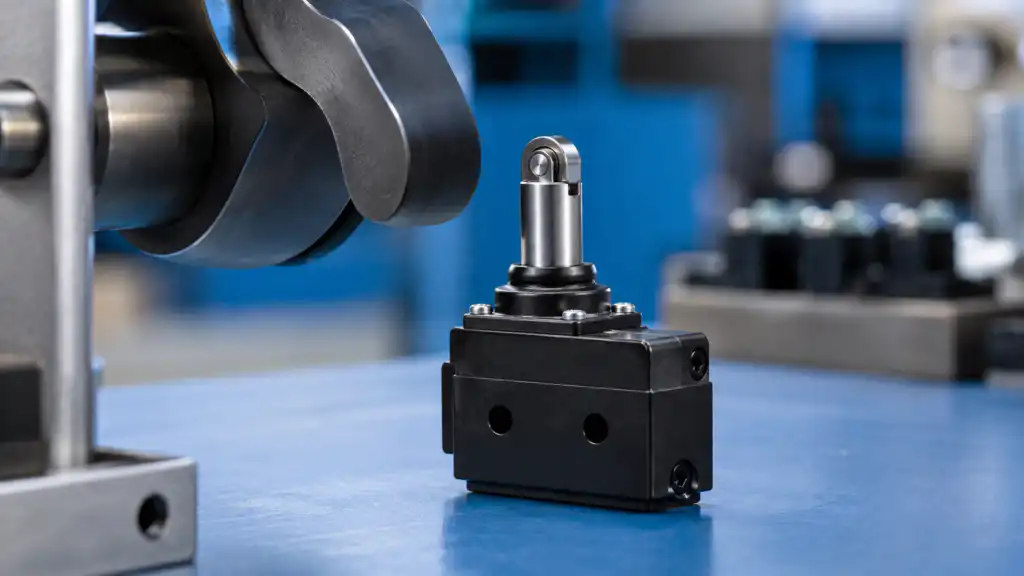
Un interruptor de límite de émbolo con rodillo combina el movimiento directo del émbolo con un pequeño elemento rodante en el punto de contacto. Es útil cuando una leva se aproxima generalmente a lo largo del eje del émbolo, pero también se desplaza lateralmente a través del interruptor. El rodillo puede reducir la fricción por deslizamiento y el desgaste superficial en comparación con un émbolo plano. No corrige una mala alineación, un impacto excesivo, un recorrido excesivo insuficiente o una envolvente inadecuada. La selección debe comenzar con la trayectoria de la leva, la velocidad de aproximación, la fuerza de operación, el recorrido permitido, la repetibilidad y el entorno, seguidos de una validación en la máquina ensamblada.
Regla de selección: trate el dispositivo, el actuador, los contactos, la carcasa, el cableado, la lógica de control, el usuario y el movimiento de la máquina como un solo sistema. Los ejemplos de productos ilustran únicamente la forma; la idoneidad final debe provenir de la documentación actual para el código de pedido exacto y de la validación en el equipo terminado.
Cómo funciona el mecanismo
A medida que la leva entra en contacto con el rodillo, el émbolo se mueve hacia el cuerpo del interruptor. El mecanismo interno cambia de estado en el punto de operación y regresa después de que la leva retrocede más allá del punto de liberación. La diferencia crea una histéresis útil. El rodamiento de rodillos, la guía del émbolo, los sellos, el resorte de retorno y los contactos internos contribuyen al comportamiento. Una leva que se desplaza demasiado profundo o golpea desde un lado puede dañar el mecanismo incluso cuando el circuito eléctrico es correcto.

Criterios de selección de un vistazo
| Área de decisión | Qué verificar | Razón de ingeniería |
|---|---|---|
| Perfil de leva | Utilice una introducción y una conclusión fluidas compatibles con el dibujo del interruptor | Los bordes afilados generan impacto y movimiento inestable. |
| Dirección de aproximación | Mantenga la fuerza resultante cerca del eje del émbolo permitido | La fuerza lateral puede trabar la guía o acelerar el desgaste. |
| Operando viajes | Cruzar el punto de operación bajo cualquier condición de tolerancia | Una carrera demasiado corta provoca señales perdidas. |
| Masificación turística | Proporcionar margen sin alcanzar el límite mecánico | El exceso de carrera controlado absorbe la variación sin usar el interruptor como tope. |
| Velocidad | Compara las velocidades mínima y máxima de la leva con los límites del dispositivo | El movimiento muy lento o rápido puede cambiar el comportamiento de conmutación y el impacto. |
| Material del rodillo | Relacione las superficies del rodillo y de la leva con las condiciones de desgaste y contaminación | Un rodillo sigue siendo una interfaz de contacto mecánico. |
| Rigidez de montaje | Evitar el movimiento de los soportes y el aflojamiento de los sujetadores | Pequeños desplazamientos de montaje cambian el punto de operación. |
| Medio ambiente | Verifique la entrada, la temperatura, el aceite, las virutas, la vibración y el sellado de cables | La protección debe aplicarse al conjunto completo instalado. |
Esta tabla es intencionalmente cualitativa. Los límites numéricos, clasificaciones, par, fuerza, recorrido, declaraciones ambientales y valores de resistencia deben tomarse de la hoja de datos actual y evaluarse bajo las condiciones de la aplicación.
Proceso de selección detallado
Perfil de leva
Qué verificar: Utilice una entrada y una salida suaves compatibles con el dibujo del interruptor. Los bordes afilados crean impacto y un movimiento inestable. El requisito debe escribirse en la especificación del proyecto y rastrearse hasta el dibujo del modelo exacto o la hoja de datos. Revise la tolerancia en el peor de los casos, el desgaste, la contaminación, el acceso para mantenimiento y el uso indebido previsible. Si la documentación disponible no define el límite, mantenga el punto abierto para la confirmación del proveedor y la prueba de muestras en lugar de sustituirlo por una suposición.
Dirección de aproximación
Qué verificar: Mantenga la fuerza resultante cerca del eje permitido del émbolo. La fuerza lateral puede atascar la guía o acelerar el desgaste. El requisito debe escribirse en la especificación del proyecto y rastrearse hasta el dibujo del modelo o la hoja de datos exacta. Revise la tolerancia en el peor de los casos, el desgaste, la contaminación, el acceso para mantenimiento y el uso indebido previsible. Si la documentación disponible no define el límite, mantenga el punto abierto para la confirmación del proveedor y la prueba de muestras en lugar de sustituirlo por una suposición.
Operando viajes
Qué verificar: Cruzar el punto de operación bajo todas las condiciones de tolerancia. Un recorrido insuficiente provoca señales perdidas. El requisito debe redactarse en la especificación del proyecto y rastrearse hasta el plano de modelo exacto o la hoja de datos. Revise la tolerancia del caso peor, el desgaste, la contaminación, el acceso para mantenimiento y el uso indebido previsible. Si la documentación disponible no define el límite, mantenga el punto abierto para la confirmación del proveedor y la prueba de muestras en lugar de sustituirlo por una suposición.
Masificación turística
Qué verificar: Proporcione margen sin alcanzar el límite mecánico. El sobrerrecorrido controlado absorbe la variación sin utilizar el interruptor como tope. El requisito debe redactarse en la especificación del proyecto y rastrearse hasta el plano del modelo exacto o la hoja de datos. Revise la tolerancia en el peor de los casos, el desgaste, la contaminación, el acceso para mantenimiento y el uso indebido previsible. Si la documentación disponible no define el límite, mantenga el punto abierto para la confirmación del proveedor y la prueba de muestras en lugar de sustituirlo por una suposición.
Velocidad
Qué verificar: Compare la velocidad mínima y máxima de la leva con los límites del dispositivo. Un movimiento muy lento o rápido puede cambiar el comportamiento de conmutación y el impacto. El requisito debe escribirse en la especificación del proyecto y rastrearse hasta el plano del modelo exacto o la hoja de datos. Revise la tolerancia en el peor de los casos, el desgaste, la contaminación, el acceso para mantenimiento y el uso indebido previsible. Si la documentación disponible no define el límite, mantenga el punto abierto para la confirmación del proveedor y las pruebas de muestras en lugar de sustituirlo por una suposición.
Material del rodillo
Qué verificar: Relacione las superficies del rodillo y de la leva con las condiciones de desgaste y contaminación. Un rodillo sigue siendo una interfaz de contacto mecánico. El requisito debe redactarse en las especificación del proyecto y rastrearse hasta el plano del modelo exacto o la ficha técnica. Revise la tolerancia en el peor de los casos, el desgaste, la contaminación, el acceso para mantenimiento y el uso indebido previsible. Si la documentación disponible no define el límite, mantenga el punto abierto para la confirmación del proveedor y las pruebas de muestras en lugar de sustituirlo por una suposición.
Rigidez de montaje
Qué verificar: Evite el movimiento de los soportes y el aflojamiento de los elementos de sujeción. Los pequeños desplazamientos de montaje cambian el punto de operación. El requisito debe escribirse en la especificación del proyecto y rastrearse hasta el plano de modelo exacto o la hoja de datos. Revise la tolerancia del peor caso, el desgaste, la contaminación, el acceso para mantenimiento y el uso indebido previsible. Si la documentación disponible no define el límite, mantenga el punto abierto para la confirmación del proveedor y la prueba de muestras en lugar de sustituirlo por una suposición.
Medio ambiente
Qué verificar: Verifique la entrada, temperatura, aceite, virutas, vibración y sellado de cables. La protección debe aplicarse a todo el conjunto instalado. El requisito debe redactarse en la especificación del proyecto y rastrearse hasta el dibujo del modelo exacto o la hoja de datos. Revise la tolerancia en el peor de los casos, el desgaste, la contaminación, el acceso para mantenimiento y el uso indebido previsible. Si la documentación disponible no define el límite, mantenga el punto abierto para la confirmación del proveedor y la prueba de muestras en lugar de sustituir una suposición.

Revisión de la solicitud
- Confirmación de la posición del transportador. Registre el comando esperado, la respuesta, el comportamiento de liberación, la condición anormal y la evidencia de aceptación para la máquina ensamblada.
- Detección de inicio de la mesa divisora. Registre el comando esperado, la respuesta, el comportamiento de liberación, la condición anormal y la evidencia de aceptación para la máquina ensamblada.
- Retroalimentación de la posición de la puerta o cubierta en un mecanismo protegido. Registre el comando esperado, la respuesta, el comportamiento de liberación, la condición anormal y la evidencia de aceptación para la máquina ensamblada.
- Control de secuencia accionado por leva. Registre el comando esperado, la respuesta, el comportamiento de liberación, la condición anormal y la evidencia de aceptación para la máquina ensamblada.
- Retroalimentación de posición final donde el desplazamiento lateral de la leva es inevitable. Registre el comando esperado, la respuesta, el comportamiento de liberación, la condición anormal y la evidencia de aceptación para la máquina ensamblada.
Para cada aplicación, incluya el inicio, la operación normal, el apagado, la pérdida de energía, la restauración de energía, el modo de mantenimiento, el reemplazo de componentes y las fallas identificadas por la evaluación de riesgos. Un interruptor de control general no debe tratarse como una función de seguridad completa.
Lista de verificación de puesta en marcha
- Congelar el requisito. Indique la acción prevista, condición normal, alimentación, carga, movimiento, entorno y usuario.
- Coincidir con el código de pedido. Compare la pieza entregada con el dibujo aprobado, el esquema de contactos, el actuador, el tipo de terminal y los accesorios.
- Inspeccionar la instalación. Verificar alineación, elementos de sujeción, holgura trasera, recorrido de cables, alivio de tensión, protección de partes activas y acceso para mantenimiento.
- Prueba cada estado. Verificar el funcionamiento y la liberación en los extremos de tolerancia, velocidades previstas, cargas, guantes, contaminación y condiciones ambientales.
- Probar condiciones anormales. Incluya conductores desconectados, mecanismos bloqueados o dañados, pérdida de energía, contaminación y otras fallas creíbles.
- Registrar el resultado. Guardar modelo, revisión, método de prueba, observaciones, criterios de aceptación, fecha y aprobador.
Errores comunes
- Conducir el rodillo más allá de su carrera permitida. Evite esto asignando la comprobación a un plano, hoja de datos, registro de cableado o prueba de puesta en marcha con un criterio de aceptación nombrado.
- Colocar la esquina de la leva directamente contra el rodillo. Evite esto asignando la comprobación a un plano, hoja de datos, registro de cableado o prueba de puesta en marcha con un criterio de aceptación nombrado.
- Tratar el interruptor como una función de seguridad sin una arquitectura validada. Evite esto asignando la comprobación a un plano, hoja de datos, registro de cableado o prueba de puesta en marcha con un criterio de aceptación nombrado.
- Seleccionando solo de la corriente de contacto. Evite esto asignando la comprobación a un plano, hoja de datos, registro de cableado o prueba de puesta en marcha con un criterio de aceptación nombrado.
- Pruebas únicamente en alineación nominal. Evite esto asignando la comprobación a un plano, hoja de datos, registro de cableado o prueba de puesta en marcha con un criterio de aceptación nombrado.
Qué incluir en una solicitud de cotización (RFQ)
Proporcione la aplicación, el mercado objetivo, las normas aplicables, la función de la máquina, la alimentación y la carga, la interfaz de control, la lógica de contactos, el dibujo mecánico, la trayectoria de movimiento, las dimensiones del panel, el método de cableado, el entorno, la frecuencia de operación, la cantidad, las necesidades de documentación y el plan de validación de muestras. Pida al proveedor que identifique las suposiciones y excepciones. ONPOW ofrece productos relevantes en su familia de productos específica de la aplicación y lo más amplio gama de productos de control industrial.
Guías relacionadas de ONPOW
- Cómo funciona un microinterruptor
- Microinterruptor vs interruptor de límite
- Vida mecánica vs. vida eléctrica
Referencias autorizadas
- aparatos para circuitos de control IEC 60947-5-1
- IEC 60529 grados de protección proporcionados por las envolventes
- Requisitos de protección de maquinaria de OSHA
- Requisitos de seguridad eléctrica de OSHA
Video educativo
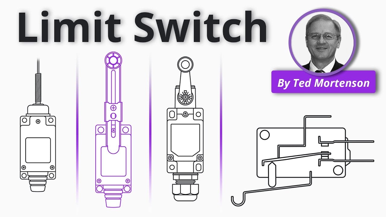
Limit Switch Explained de RealPars proporciona antecedentes generales. Las decisiones de proyecto aún requieren las normas aplicables y la documentación del producto.
Preguntas frecuentes
¿Por qué usar un rodillo en lugar de un desatascador plano?
Un rodillo puede reducir la fricción por deslizamiento cuando una leva en movimiento pasa a través del actuador.
¿Puede la leva acercarse desde cualquier dirección?
No. Utilice la dirección y el ángulo permitidos por el plano exacto del fabricante.
¿Cuánta sobrecarrera se necesita?
Suficiente para mantener la operación dentro de las tolerancias sin exceder el límite documentado; utilice los datos exactos del modelo.
¿Mejora un émbolo de rodillo la clasificación eléctrica?
No. El estilo del actuador no reemplaza la verificación de voltaje, corriente, categoría de carga y corriente de entrada.
Decisión final
Apruebe el componente únicamente cuando los límites documentados de mecánica, electricidad, medio ambiente, usabilidad, instalación y mantenimiento se ajusten al sistema ensamblado. Resuelva las incógnitas mediante información actual del fabricante y pruebas antes de la liberación para producción.
Personalización
ONPOW undertakes a variety of custom needs for push-button development. Confirm whether packaging, marking or documentation OEM/ODM applies to Roller Plunger Limit Switch Selection for Industrial Machines in the quotation.
La cantidad mínima de pedido, el plazo de entrega y los términos comerciales no se publican aquí; confirme estos datos con la atención comercial. sales@onpow.com.



