

Micro switch travel terms describe where the actuator starts, where the contacts operate, how much permitted movement remains after operation, and where the contacts reset during release. Pretravel is movement before operation; overtravel is movement beyond the operating point within the specified allowance; differential movement is the separation between operating and release positions. Read each value using the manufacturer’s reference point and actuator definition. These terms help determine whether a target will operate and release reliably without overloading the switch. They are not universal dimensions, and the target must not use the switch’s internal end position as a machine stop.
Put every position on the same coordinate system
Start with the exact actuator drawing. Identify the free position, operating position, release position, and permissible final position. Some drawings specify displacement from a free position; others use dimensions from a mounting reference. Do not combine those values without translating them to the same coordinate system.
A lever or roller can also have a stated measurement point. Travel at the lever end differs from movement near its pivot. The target’s direction and the actuator’s permitted motion need to match the drawing. A dimension along one axis is not necessarily the target’s total path length.
For the basic mechanism, see how a micro switch works. For target interfaces, see micro switch roller and cam geometry. This article concentrates on interpreting travel and planning margins.
Pretravel: movement before the contact changes
Pretravel is the actuator movement from the defined free position to the operating point. The target needs to provide enough movement to cross that point under the least favorable combination of tolerances. Merely touching the plunger or lever does not prove the contact has transferred.
Check whether the data provide a nominal operating point, maximum pretravel, or a range. Those descriptions are not interchangeable. For a guaranteed operating check, use the applicable limit and account for mounting and target variation. If the information is missing, request it rather than estimating from the visible actuator height.
A cam that only grazes the actuator can create intermittent operation as the target or bracket shifts. Increase the reliability of the geometry through a reviewed arrangement, not by assuming that snap action eliminates the need for sufficient travel.
Overtravel: permitted movement after operation
After the contact changes, the target may continue moving. Overtravel describes the further permitted actuator movement according to the product’s definitions. It provides installation tolerance and operating dwell, but it is not permission to press indefinitely or collide with the actuator.
The machine must stay within the permitted final position at its most compressed tolerance condition. An external stop, appropriate cam profile, or another mechanical design measure should control excessive movement. Do not let a moving carriage stop against the switch simply because the contact has already changed.
| Term | Practical meaning | Installation check |
|---|---|---|
| Free position | Defined actuator position without operating input | Confirm target withdrawal and reference geometry |
| Operating position | Position where the specified contact transition occurs | Reach it at the least favorable approach condition |
| Pretravel | Movement from the free position to operation | Include target, bracket, and actuator tolerances |
| オーバーツーリズム | Specified allowed movement after operation | Avoid exceeding the permitted final position |
| Release position | Position where the contact resets on return | Allow enough withdrawal for reliable release |
| Differential movement | Difference between operating and release positions | Check hysteresis against target dwell and vibration |
The table uses common conceptual meanings. The exact drawing may use different symbols or dimension references; the selected model’s definitions govern the calculation.
Differential movement explains why reset happens elsewhere
A snap-action mechanism typically operates and releases at different positions. The separation is mechanical hysteresis. That is why backing the target away by a barely visible amount may not reset a contact immediately after operation.
The difference can help prevent switching around one exact point, but its usefulness depends on the target’s motion. If the target oscillates across both operating and release positions, the switch can still change repeatedly. The mounting and control logic need a defined response to that movement.
Record the contact state while approaching and while withdrawing. The same physical position within the hysteresis band can correspond to different states depending on motion history. Do not interpret that observation as a wiring fault without checking the mechanism’s declared behavior.
Calculate margins with explicit limits and units
Use a consistent displacement coordinate that increases in the operating direction. Let xOP be the relevant operating position, xRP the release position, and xMAX the permissible maximum actuator position. Let xTARGET be the target’s imposed actuator position after accounting for the mechanical interface. Use millimetres throughout, or another single compatible length unit.
An operating margin can be expressed as xTARGET,min − xOP,max. A positive result indicates that the least target movement crosses the maximum applicable operating position under the stated assumptions. A remaining-travel margin can be expressed as xMAX,min − xTARGET,max. A positive result indicates that the greatest target movement stays within the minimum applicable permissible final position.
For release, check that the withdrawn target allows the actuator to return past the required release position. The direction of the inequality depends on the chosen coordinate and product definitions. Write that convention in the calculation rather than copying a formula blindly.
As a purely illustrative example, an imposed position range of 1.6–1.9mm with a maximum operating position of 1.4mm and a minimum permissible final position of 2.2mm gives 0.2mm operating margin and 0.3mm remaining-travel margin. These invented example values are not ONPOW specifications. They only show why the two checks must be performed separately.
Include the complete mechanical tolerance chain
The actuator’s travel range is only one contributor. Mounting-hole location, bracket adjustment, target dimensions, bearing play, housing movement, cable loads, and temperature can change the relative position. Some contributors affect approach and release differently.
List each contributor with its physical direction and effect. Determine the relevant extreme combination for missed operation, excessive compression, and failed release. A single average margin can hide a failure at one end of the mechanism’s movement range.
If the available margins are inadequate, change the reviewed geometry, improve support, or choose another actuator. Do not declare the installation acceptable because it works when pressed by hand. A controlled target path with adequate margins is more meaningful than a one-time click.
Use the actuator’s measurement point correctly
A lever converts target movement into movement at the internal mechanism. Travel at a long lever tip can be greater than travel at a shorter contact point. An angled cam can also create a varying displacement relationship across the stroke. Keep the manufacturer’s stated measurement point in the analysis.
For a pin plunger, off-axis rubbing can prevent free movement and make the observed reset inconsistent. For a roller actuator, cam profile and direction influence the contact path. Check allowed actuation direction and speed with the exact product guidance.
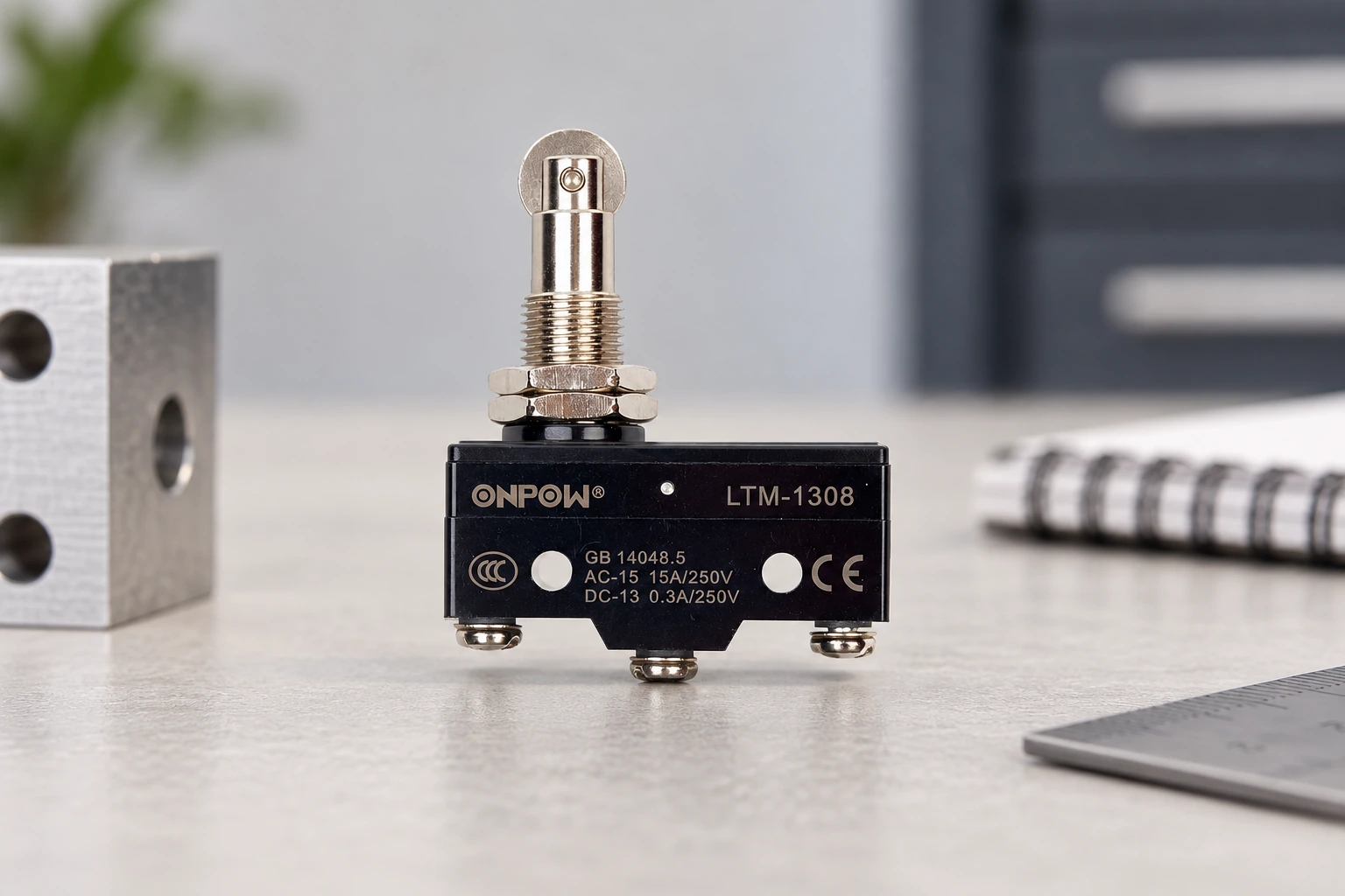
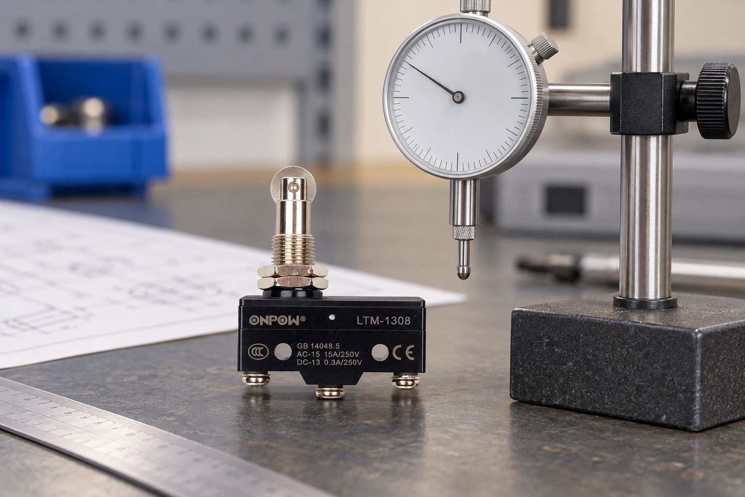
A real ONPOW LTM-1308 example appears in the illustrations. They show its physical roller-plunger form, not measured travel limits. Obtain the current drawing and applicable force/travel data before setting the target.
Connect travel behavior to the electrical observation
The contact diagram defines the normal and operated paths, but the mechanism determines when they change. An input that appears late may result from insufficient target movement, receiver filtering, or program timing. Separate those causes by comparing physical actuator position, isolated contact behavior, and the receiving input through the approved test procedure.
A continuity instrument may identify stable contact states but cannot establish every short transition or the electrical life of the contact. For timing-sensitive events, use the measurement method specified by the equipment’s engineering test plan. Do not hide a marginal travel arrangement behind excessive input filtering.
その limit-switch NO/NC wiring guide covers related circuit interpretation. The IEC 60947-5-1 publication gives standards context for electromechanical control devices, without supplying dimensions for a particular product.
Verify travel safely and preserve the adjustment
Qualified personnel should inspect installed machinery under the applicable energy-control procedure. Stored motion and electrical energy can remain even when a controller indicates stopped. Relevant United States requirements include 29 CFR 1910.147 そして 29 CFR 1910.333.
Measure the relevant positions with a supported fixture and appropriate instruments. Stay within permissible movement; testing is not a reason to push to an unspecified internal stop. During authorized operational commissioning, verify approach, operated dwell, withdrawal, and release across the expected mechanism conditions.
Record the bracket position, adjustment reference, part suffix, drawing revision, measured results, and acceptance limits. Mark or document the approved setting using the equipment’s maintenance method. A later bracket or actuator change should trigger review rather than inheriting an old travel result.
教育ビデオ
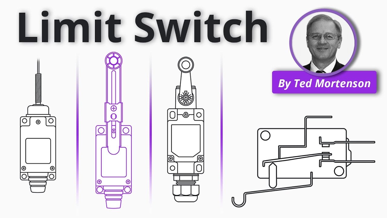
Limit Switch Explained | Working Principles by RealPars. General educational background. Use the selected product drawing and the machine design for the actual circuit and installation. Watch on YouTube.
よくある質問
Is pretravel the total allowed stroke?
No. It describes movement before contact operation. Permitted movement after operation and the final position require separate confirmation.
Does overtravel mean the switch can stop a moving target?
No. It is a specified actuator allowance, not a machine-stop rating. The mechanical design must control excessive target movement.
Why can the same actuator position show two contact states?
Within the operating-to-release hysteresis band, state can depend on whether the actuator is approaching or withdrawing. Check the exact mechanism’s behavior.
Can I compare lever and plunger travel directly?
Only after understanding their measurement references and geometry. Travel at different actuator points can represent different target movement.
What should a supplier provide for a travel review?
The exact actuator drawing, operating and release definitions, applicable travel limits, force data, allowed actuation direction, and mounting instructions are required.



