

Push button panel cutout preparation is the inspection and finishing work that makes a specified opening ready for the ordered switch. A hole can have the correct nominal diameter yet still be unsuitable because of burrs, distortion, coating defects or an uneven sealing face. Use the approved product drawing to define the opening, then inspect the finished panel and both sides of the edge before assembly. Do not enlarge the hole by feel, use the retaining nut to flatten damaged metal, or assume that a switch’s front protection rating compensates for poor panel workmanship.
Start with the finished-panel requirement
The fabrication instruction should identify the exact button, the applicable drawing revision and the condition in which dimensions are accepted. A raw punched hole and a coated finished opening are not necessarily the same geometry. Paint or other finishing processes can change the edge condition and the available opening, while subsequent scraping can remove protection or leave an irregular sealing surface.
A general description such as a nineteen-millimeter button is not a complete hole specification. Some products require an antirotation feature, a particular opening shape or other drawing details. Confirm those requirements instead of assuming that every round-looking head fits an interchangeable circular hole. Where the drawing is incomplete, obtain clarification before releasing the panel for production.
The 패널 장착 푸시 버튼 가이드 covers broader installation choices. This article focuses on the quality of a specified cutout after fabrication. Diameter selection, the allowable thickness stack and mounting torque remain separate decisions with their own documented limits.
Identify where the panel meets the assembly
Review the front seating area, the opening edge and the rear clamping area. Each can affect fit or assembly. A projection on the front can prevent even seating. A sharp or damaged opening edge can interfere with insertion or handling. A rear burr can distort clamping or create an unsafe edge near wiring and maintenance access.
For a sealed assembly, identify the intended sealing interface from the manufacturer’s instructions. Do not infer gasket placement solely from a product photograph. Some assemblies contain a supplied seal in a defined position; others have different arrangements. An extra washer or improvised seal can change the clamp stack and may place pressure where it was not intended.
The LAS1GQ-11E/L/S 제품 페이지 provides a relevant threaded metal-button example. Use its current approved drawing for the ordered configuration. The product image establishes the visible construction, while the panel drawing and assembly instruction establish how that construction is meant to fit.
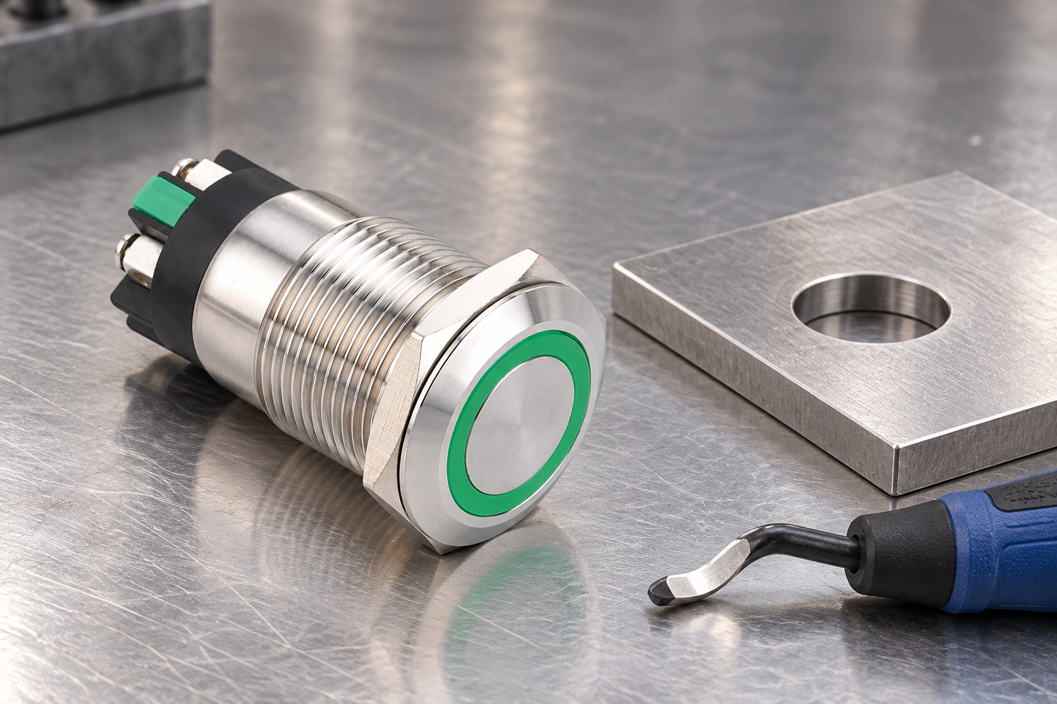
Distinguish burr removal from dimensional rework
Deburring removes unwanted edge projections. It should not become uncontrolled enlargement, countersinking or reshaping of the opening. Removing too much material may reduce support, change the seating area or create a geometry that no longer matches the drawing. A visually neat chamfer is not automatically permitted at a sealing interface.
Choose a fabrication and finishing method appropriate to the panel material, coating process and specified edge condition. Punching, drilling, laser cutting and machining can leave different defects. The process plan should identify what must be inspected after the chosen method. Do not copy a finishing instruction from a different material without checking its effect on dimensions and the final surface.
If the hole is already oversize, distorted or in the wrong position, stop for an approved disposition. Further hand finishing cannot restore missing material. Likewise, tightening the button against a defective opening does not create an acceptable repair. Rework must be authorized, controlled and re-inspected; where a compliant repair is unavailable, replace the panel rather than concealing the defect under a bezel.
Inspect both sides before assembly
Perform the inspection while the panel is accessible and before wiring makes the rear difficult to see. Use suitable lighting and inspection methods that do not expose fingers to sharp edges. Check for raised lips, attached slivers, sharp projections, local distortion and residue around the complete circumference. Inspect required locating features as carefully as the main opening.
Measure the relevant finished dimensions with suitable equipment and a defined method. Record actual results against the drawing rather than writing fits after pushing one sample button into the hole. A forceful trial insertion can scratch the barrel, displace a seal or hide a tolerance problem. It also says little about whether the next assembly in production will fit.
For general tool-safety requirements, consult the HSE work equipment and machinery guidance. Tool condition and an appropriate work method are part of safe fabrication. That guidance does not define ONPOW hole tolerances or authorize a particular chamfer; those requirements must come from the approved engineering documents.
Use a practical cutout acceptance checklist
The following table is qualitative and must be completed with the actual drawing and process criteria. It deliberately avoids universal burr heights, edge radii or roughness limits. Those numbers depend on the specified design and must not be borrowed from an unrelated component.
| Inspection area | What to establish | Action when the requirement is not met |
|---|---|---|
| Finished opening geometry | Size, shape and required locating features match the drawing | Hold the panel for approved rework or replacement |
| Front seating area | Flat, clean surface compatible with the specified seal and bezel | Resolve distortion, residue or coating defects before assembly |
| Opening edge | No unacceptable projections or uncontrolled material removal | Apply only the approved finishing process and inspect again |
| Rear clamping area | Suitable support without trapped slivers or raised material | Remove defects under the process instruction and recheck |
| Coating condition | Finished edge protection and dimensions meet the panel specification | Obtain an approved coating repair or rework disposition |
| Cleanliness | No loose conductive chips or abrasive residue remain | Clean and inspect the panel before electrical assembly |
Record the inspection stage and responsible person so the assembly team knows whether it is receiving a finished accepted panel or a part awaiting rework. Photographs of a defect help communication, but they do not replace measurements where dimensions determine acceptance. Retain the approved disposition with any reworked panel.
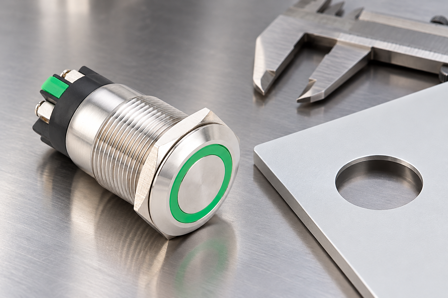
Protect the sealing face during finishing
A sealing surface should not be used as a convenient abrasive work area. Follow the specified finishing direction and protect adjacent coated or finished areas. Remove debris without introducing chemicals that have not been approved for the panel finish and seal materials. A cleaner that makes bare metal look attractive may be unsuitable for a nearby polymer or coating.
Do not leave loose chips inside a control enclosure. Conductive debris creates problems beyond the appearance of the cutout and can migrate into terminals or equipment. Complete machining, deburring and cleaning before sensitive components are installed whenever the process allows. If rework on an assembled panel is unavoidable, use a specifically approved protection and cleaning procedure.
The IEC 60529 standard page identifies the standard for the protection-code framework. It does not certify a complete panel assembled under arbitrary conditions. The IP65 versus IP67 sealing guide explains why the product’s protection claim and the finished installation must be considered together. Treat the seal, panel and mounting arrangement as a documented combination.
Check thickness and clamping separately
Once the opening passes inspection, confirm that the total mounting stack is within the ordered product’s permitted range. Include the panel, coating and any documented accessory or seal as the assembly instruction requires. A clean cutout does not compensate for inadequate thread engagement or an unapproved washer stack.
사용하기 panel thickness and mounting stack guide for this separate axial check. Keep its acceptance record distinct from the hole inspection. If a button will not seat, identify whether the obstruction comes from opening geometry, a seal position, stack thickness or the wrong component before applying more force.
Then follow the approved nut-tightening instruction. The mounting nut torque guide addresses the assembly process. Never increase tightening effort to pull a warped panel flat or to force a barrel through a tight hole. An assembly that needs such force should return to inspection with its cause recorded.
Control production changes and replacement panels
A change in cutting tool, supplier, material thickness or coating process can affect the final opening even when the nominal drawing remains unchanged. Define which changes require renewed inspection or a sample assembly review. Keep process acceptance linked to the finished product, rather than assuming a previously successful raw-hole dimension remains sufficient indefinitely.
For replacement panels, use the current approved revision and verify that the replacement button has not changed. Similar heads may have different rear construction or locating details. Compare complete part identities before drilling or filing. Maintenance staff should not discover a mismatch only after the original panel has been removed and production is waiting.
Send ONPOW the complete button code, panel material and finish, drawing revision and photographs when asking for fit assistance. Provide measured finished-hole results and the proposed mounting stack. Ask for the required cutout and assembly conditions rather than a generic assurance that the switch is waterproof. A clear drawing-based request helps resolve fit and sealing questions before parts are damaged.
자주 묻는 질문
Is the correct nominal hole diameter enough?
No. The finished opening must also meet the specified shape, edge, surface and assembly requirements. Burrs, distortion and coating defects can prevent proper fit even when one diameter measurement appears acceptable.
Should every push button cutout be chamfered?
Do not assume so. Apply only the edge treatment permitted by the approved panel and product instructions. An uncontrolled chamfer can change the support or sealing interface and may require engineering review.
Can the retaining nut flatten a raised burr?
It should not be used as a repair tool. Hold the panel, remove the defect through an approved process and inspect it again. Tightening over trapped material can conceal an unsuitable clamping surface.
Does an IP67 button make a rough opening acceptable?
No. A component protection rating does not excuse a defective mounting interface. Confirm the specified seal, panel condition, mounting stack and assembly process, then validate the finished installation as required.
Further learning
University dimensional metrology lesson on measuring tools. Complements finished-opening inspection; does not define ONPOW cutout tolerances or edge treatment.
Linear measuring instruments – 2 (Combination set, Vernier calipers) — nptelhrd



